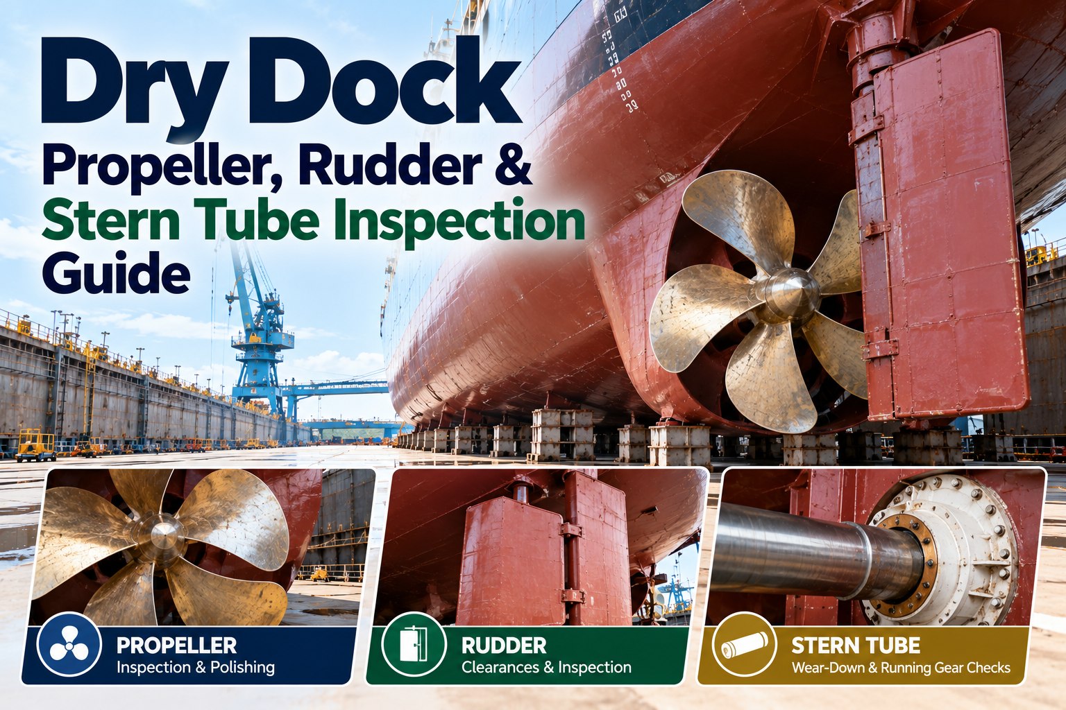
Dry Dock Propeller, Rudder & Stern Tube Inspection Guide
For about sixty months the running gear tells you nothing directly. You get vibration, bearing temperatures, oil analysis and a slow deterioration in the speed and power curve, and from those you infer. Then for ten days the ship sits on blocks and every one of those inferences can be replaced with a measurement — after which the water comes back and you are inferring again for another five years.
Dry dock · propeller, rudder and stern tube
Five years of inference, ten days of measurement
Every clearance, every docking, in one place instead of six survey reports
Tailshaft survey: what the interval actually depends on
Before planning the work it is worth being clear about which survey this docking is. The requirements differ sharply between oil-lubricated and open water-lubricated systems, and the interval is not a single number.
Oil-lubricated, closed system
A five-year interval applies across flanged, keyless and keyed propeller connections. For keyless connections the maximum interval between two surveys carried out by the fuller methods must not exceed 15 years, reached only after at most two consecutive surveys by the lightest method, with one extension of no more than three months.
Water-lubricated, open system
Every three years where the shaft has no corrosion protection, and every five years where it has adequate means of corrosion protection or operates exclusively in fresh water. The survey involves full extraction and examination of the entire shaft, including liners and the corrosion protection system.
Method 1
Shaft drawn
The shaft is withdrawn and the entire shaft, seal system and bearings examined, with the propeller removed and non-destructive examination of the taper section including the keyway where fitted. Bearing clearances checked and recorded.
Method 2
In place, with crack detection
No full extraction, but non-destructive examination by an approved surface crack detection method, and bearing wear-down measurements checked and recorded.
Method 3
Visual plus measurement
Visual inspection of all accessible parts of the shafting system together with bearing measurements. Not permitted for keyed connections, and only two of these may run consecutively.
Two documentation items are easy to lose and expensive to be without. Lubricating oil analysis is required at intervals not exceeding six months with the records retained on board, and the oil sample is examined in the presence of the surveyor with particular attention to water contamination. Arriving at the docking without twelve months of analyses is how a straightforward survey becomes a conversation.
Stern tube bearing wear-down
Wear-down is the measurement that decides whether the bush has years left or is becoming the reason for the next docking. It is taken with a poker gauge through the aft seal housing, and the discipline around it matters more than the technique.
Take it at the same point, every time
Readings are only comparable if the gauge goes into the same place in the same orientation. Record the position as carefully as the number, because the next superintendent will not be the one who took this reading.
Measure before anything is disturbed
Before the propeller is touched, before the seal is opened, before staging loads anything. A wear-down figure taken after work has started describes the work, not the bearing.
Read the slope, not the figure
A single reading inside limits says very little. Three dockings of readings give a rate, and the rate is what tells you whether the bush reaches its limit before or after the next scheduled survey.
Treat a jump as a cause, not a number
Wear that accelerates between cycles usually points at something else — alignment, lubrication, a seal that has been passing, or a period of heavy operation. The reading is the symptom.
The limits themselves are set by the bearing material and the builder’s drawings, and confirmed by class, so the figure to compare against belongs in the docking file rather than in somebody’s memory. The shaft line as a system — lubrication philosophy, failure modes and alignment — is covered in our guide to propeller and shaft maintenance; this page is about the measurements the docking makes possible.
Rudder clearances: the four dimensions that matter
Rudder work is where dockings get interesting, because the clearances are straightforward to measure, strictly limited, and almost never trended. Four dimensions carry the assessment.
That last relationship is the one worth carrying away from this section. The protection clearance exists so that if the rudder or skeg strikes the bottom, the rudder rises and is stopped before the load reaches the steering gear. If wear has eaten into it until it approaches the jumping clearance, the arrangement has quietly stopped protecting anything — and the first indication will be a steering gear casualty rather than a rudder repair. The steering side of that system is covered in our guide to steering gear hydraulic maintenance and testing.
Maximum rudder clearance by stock diameter
Clearance limits follow the rudder arrangement and the stock diameter rather than a single figure, which is why a reading means nothing until it is put against the right formula. The worked examples in the last column are there to save the arithmetic on the day.
Rudder arrangement
Stock diameter D
Maximum clearance
Worked example
Types 1 to 3 and 5
50 mm or less
3.0 mm
Small craft only; the figure is fixed
Types 1 to 3 and 5
Over 50 mm to 100 mm
0.02D + 2 mm
D = 80 mm gives 3.6 mm
Types 1 to 3 and 5
Over 100 mm
0.005D + 3.5 mm, capped at 7.5 mm
D = 300 mm gives 5.0 mm; D = 500 mm gives 6.0 mm; D = 800 mm reaches the 7.5 mm cap
Types 4 and 6 to 10
50 mm or less
2.5 mm
Small craft only; the figure is fixed
Types 4 and 6 to 10
Over 50 mm
0.007D + 2.2 mm, capped at 6.0 mm
D = 300 mm gives 4.3 mm; D = 500 mm gives 5.7 mm; D = 600 mm reaches the 6.0 mm cap
Figures follow the classification limits for rudder stock and pintle clearances. Confirm the arrangement type and the governing rule with the attending society before acting on a measurement, because the arrangement determines which row applies and a rudder is not always the type the drawing office assumed.
Two further points sit outside the formulas. Pintle clearances also have in-service figures that differ from initial build clearances — for a 6 inch pintle the permitted in-service clearance runs to around 2.4 mm, rising to around 5.6 mm for a 14 inch pintle. And excessive clearance found within a short period, say five years, is itself a finding: it says the rate is wrong even when the absolute number is still inside the limit.
A clearance is a trend, not a reading
Marine Inspection holds wear-down and clearance measurements against the component and the docking, so the next superintendent sees three cycles of numbers rather than one sheet from a yard that has since been changed.
What else to examine on the rudder while it is accessible
The clearances are the measurements. These are the findings that come from looking, and most of them are invisible once the ship is back in the water.
Sleeves, liners and the gap behind them
Loose sleeves admitting water, and crevice corrosion where liners contact bushes. Deep pitting next to stainless steel sleeves is a recognised pattern worth looking for specifically.
Welds and plating
Fractures at slot welds, around access plates and at internal stiffening. These are the locations that matter structurally and the ones a general walk-round misses.
Stock condition and coupling
Cone coupling slippage, keyway integrity checked by non-destructive examination, and any sign of a bent or twisted stock. Deformation of the horn belongs in the same check.
Swing the rudder before undocking
After any repair, the rudder should be swung in the dock wherever it can be, to confirm free movement. A clearance measured correctly on a rudder that binds is still a problem discovered at sea.
If a stock is found twisted, the acceptance criteria are tiered by the angle of twist against the ratio of length to diameter: below that ratio the stock can be accepted without heat treatment if it is free of cracks; between one and five times it requires stress relief; beyond five times it needs full annealing or normalising. All repairs go through an approved proposal with non-destructive testing to verify them.
Propeller finish: what to specify, not just that it is polished
Propeller polishing is usually bought as an activity rather than a result, which is why two ships can leave the same dock with the same line on the invoice and very different surfaces. The standard gives numbers.
Two practical consequences follow. First, the specification should name the finish to be achieved rather than the activity to be performed, because “polish propeller” has no acceptance criterion and nothing to reject against. Second, a comparator is how it is assessed on the day — the common gauge carries six samples of surface finish spanning roughly 1 to 30 microns Ra, which is enough to settle whether what you are looking at meets the class of finish you asked for.
Name the finish classSpecify the standard and the class rather than the verb, and state that the finish will be assessed against a comparator before the staging comes down.
Cover the whole bladeIncluding the root and the trailing edge, where polishing is awkward and most often skipped, and where the flow is least forgiving.
Record where you startedA roughness assessment before work begins is what turns the next polishing argument into a comparison rather than an opinion.
Expect it to be worth doingReported case studies on a 64,000 tonne bulk carrier and a 1,400 TEU container ship each put the fuel saving after polishing at around 3 per cent.
That three per cent sits alongside the hull, not instead of it. A well-polished propeller behind a fouled hull is a small gain on a large loss, which is why propeller finish belongs in the same conversation as the coating programme described in our guide to hull maintenance and inspection.
Blade damage, seals and the items that get forgotten
Blade edges
Nicks, bends and cavitation erosion recorded by blade number and radius, not as a general impression. Repairs are governed by where on the blade the damage sits, and need an approved proposal.
Seals, inboard and outboard
Condition verified on reinstatement for a closed system, and the inboard seal for an open one. A seal that was passing slightly all cycle is a seal to renew now, not to watch again.
Rope guard and rope cutter
Fastenings, distortion and anything caught behind. Cheap to deal with while accessible and a diver job for the rest of the cycle.
Propeller nut and cone
Fairing cone security and condition, and the nut arrangement checked and recorded rather than assumed because it was fine last time.
Anodes on the stern frame
Consumption and fixings, in the one place on the ship where galvanic conditions are most aggressive.
The datum for next time
Final clearances, final wear-down, finish achieved and photographs by component. This is what makes the next docking a comparison.
Sequencing running gear work in the dock
Most of what goes wrong here is ordering rather than technique. The measurements that matter have to be taken before anything else happens, and the decisions they drive have long lead times.
Before arrival
Confirm which survey method applies and what it obliges, have the oil analyses assembled, and know the previous clearance and wear-down figures and the limits they are judged against.
First hours on blocks
Wear-down and clearances taken before anything is disturbed, with the surveyor present where required. These readings are the only ones that describe the ship as she arrived.
Immediately after
Compare against limits and against the last cycle, and decide the scope the same day. Bearing renewal, seal replacement and any shaft work all carry material and specialist lead times.
Through the dock
Propeller work and rudder repair run in parallel with hull work, but both feed undocking, so they belong on the critical path rather than in the background.
Before flooding
Final clearances recorded, rudder swung to confirm free movement, finish assessed against the comparator, and everything photographed while access still exists.
Dry dock propeller and rudder inspection: frequently asked questions
How often is a tailshaft survey required?
For oil-lubricated closed systems the interval is five years across flanged, keyless and keyed connections. For keyless connections the maximum period between surveys using the fuller methods must not exceed 15 years, reached only after at most two consecutive surveys by the lightest method. Open water-lubricated shafts are surveyed every three years without corrosion protection, or every five years with adequate protection or in fresh water only.
What is the difference between the survey methods?
Method 1 draws the shaft and examines it entirely with the propeller removed and non-destructive examination of the taper. Method 2 leaves the shaft in place but requires approved surface crack detection and recorded bearing wear-down. Method 3 is visual inspection of accessible parts plus bearing measurements, is not permitted for keyed connections, and cannot run more than twice consecutively.
When should stern tube wear-down be measured?
Before anything is disturbed — before the propeller is touched, the seal opened or loads applied. Take it at the same point and orientation each docking, record the position as carefully as the figure, and judge the result by the rate of change across cycles rather than by a single reading.
What is the maximum permitted rudder clearance?
It depends on the arrangement and the stock diameter D. For types 1 to 3 and 5 it is 3.0 mm up to 50 mm, 0.02D + 2 mm from 50 to 100 mm, and 0.005D + 3.5 mm above that, capped at 7.5 mm. For types 4 and 6 to 10 it is 2.5 mm up to 50 mm and 0.007D + 2.2 mm above, capped at 6.0 mm. Confirm the arrangement type with the attending society before applying a formula.
Why does the protection clearance matter?
It must be substantially greater than the jumping clearance so that if the rudder or skeg grounds, the rudder rises and is arrested before load reaches the steering gear. Once wear has closed that margin the arrangement no longer protects the steering gear, and the failure that follows is in a far more expensive component.
Is a clearance inside limits always satisfactory?
No. Excessive clearance appearing within a short period, for example five years, is a finding in itself, because it indicates a rate of wear that will not survive to the next survey even though today’s number is still permitted.
What propeller finish should be specified?
Name the standard and the class rather than the activity. ISO 484 part 1 sets 3 microns Ra for a class S finish and 6 microns Ra for a class I finish on a new propeller, and a comparator carrying samples from about 1 to 30 microns Ra is how the result is assessed before the staging comes down.
How much does propeller polishing save?
Reported case studies on a 64,000 tonne bulk carrier and a 1,400 TEU container ship each put the saving at around 3 per cent after polishing. General surface roughness can increase by about 15 microns Ra within twelve months of service, so the gain is recoverable repeatedly rather than once.
Should the rudder be swung before undocking?
Wherever it can be, yes, particularly after any repair. It is the only confirmation of free movement available while there is still time to act on the answer.
Dry dock & planned maintenance
Arrive knowing last docking’s numbers, leave having recorded this one’s
Marine Inspection holds wear-down, clearances, survey method and scope, propeller condition and the photographs against each vessel — so the measurements that are only possible once every five years are still usable the next time the ship comes out of the water.