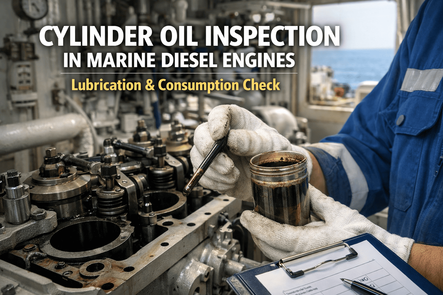
A liner wear reading means little on its own, and a wear reading taken at different points from the last one means even less. How should cylinder liner wear measurement be done, what do maker and trade sources say about rates and limits, and what should a Chief Engineer be able to show at the next overhaul or survey? This guide covers cylinder liner wear measurement and inspection on two-stroke engines in detail, with notes for four-stroke engines where sources exist. It draws on MAN Energy Solutions service letters, a 2026 report on Everllence guidance, a vendor measurement service and two trade or engine websites, and it flags where those disagree. For engine room routines, see our engine room maintenance tracking.
Where to Measure Cylinder Liner Wear: Levels, Directions and the Causes Behind Each Zone
The wear pattern depends on the zone, so the readings must be taken in the same zones
Liner wear is not uniform. A Marine Insight trade article says wear is greatest in the top third of the liner where temperature and pressure are highest, that abrasion by hard particles such as catalytic fines is worst at the dead centres, and that sulphuric acid corrosion is worst in the lower liner, producing a clover-leaf pattern. It lists friction between rings and liner, corrosion, abrasion and scuffing from insufficient lubrication as the main causes. The article is secondary, so check it against your maker's manual. The diagram shows the zones.
How to Measure Cylinder Liner Wear: Tool, Temperature, Points and Directions
Calibration: the same points, the same tool, the same temperature
The two sources that describe the method agree on the essentials. Use an internal micrometer, which an engine website says should be accurate to 0.01 mm, with a flat or template bar hung down the liner and holes drilled at each reading level so every measurement is repeated at the same place. Take readings port to starboard and forward to aft, because wear is not uniform, and take more readings near the top where wear is highest. Both the liner and the micrometer should be at the same temperature, and if they are not, a correction factor applies. The Marine Insight wording on the correction is unclear, so use the one in your manual.
The article also describes the preparation: stop and cool the engine, remove the cylinder head and piston, cover the stuffing box opening, remove the ridge and clean carbon from the top of the liner, then inspect the surface. Without lifting the piston, a vendor service from HJ Lubricators inserts a gauge through the scavenge ports and reports wear to 1/100 mm. That is the vendor's own claim, and the page gives no measuring levels and does not address ovality.
Cylinder Liner Wear Limits and Rates: What Sources Say and Where They Disagree
Rates per 1,000 hours differ by a factor of several
The published figures are not consistent, and none is from an engine maker's manual. An engine website says about 0.05 mm per 1,000 hours is ideal on a large two-stroke and about 0.015 mm on a medium-speed trunk piston engine. Marine Insight gives about 0.1 mm per 1,000 hours as normal. A vendor's sample gives 0.04 per 1,000 hours on one large engine. These are different engines and conditions, so treat the figures only as a check on whether your own rate looks odd.
Replacement wear as a share of the bore
Marine Insight gives replacement at about 0.6 to 0.8% of the bore diameter or as per the manufacturer, and the engine website gives about 0.8% of the original diameter. Neither gives an ovality limit. The table applies those percentages to common bores by our arithmetic. It shows the scale only, and the engine maker's figure decides when a liner is renewed.
| Liner bore | 0.6% of bore | 0.8% of bore |
|---|---|---|
| 500 mm | 3.0 mm | 4.0 mm |
| 600 mm | 3.6 mm | 4.8 mm |
| 700 mm | 4.2 mm | 5.6 mm |
| 800 mm | 4.8 mm | 6.4 mm |
| 900 mm | 5.4 mm | 7.2 mm |
| 980 mm | 5.9 mm | 7.8 mm |
Reading the wear pattern before you decide anything
| Pattern | Usual suggestion | What to check | Suggested action |
|---|---|---|---|
| Clover leafing in the lower liner | Acid corrosion, worse at low load or with feed rate not matched to load | Cylinder oil BN and feed rate against load, drain oil iron | Review feed rate against the maker's guidance and sulphur |
| Heavy wear at the dead centres | Abrasion by hard particles such as catalytic fines | Fuel catfines results, filters and separators | Check fuel treatment records |
| Scuffing or hard contact marks | Insufficient lubrication or a ring problem | Ring condition, feed rate, deposits | Raise feed rate as the maker advises and monitor, then plan ring renewal if damaged |
| Liner polish | A risk with some alternating oil practices on low-sulphur fuels | Surface condition and oil strategy | Follow the current maker letter, which no longer needs BN alternation with Cat. II BN 40 |
Scavenge Port Inspection and Piston Ring Checks: What the Maker's Letters Ask For
A cadence from fortnightly drain oil checks to the yearly measurement
The maker letters are the most authoritative sources here, but they apply to MAN B&W two-stroke engines and have been updated. SL2019-671 of April 2019, SL2023-737 of June 2023 and Everllence's SL2025-776, as reported by CMT in February 2026, move in the same direction: inspect often, change the feed rate in small steps and read the drain oil in context. Piston ring inspection is part of the same visit, with the 2019 letter asking for ring coating thickness and pressure relief grooves to be measured and cermet coating fitted on all piston rings and piston cleaning rings for VLSFO and ULSFO operation.
Cylinder Oil Feed Rate and Drain Oil Analysis: The Numbers in the Maker Letters
Feed rate figures and iron limits, with the caution that context matters
The table collects the figures from the two MAN letters. They apply to MAN B&W two-stroke engines and may have been superseded by the letter in force for your engine. Read them as a record of how the guidance is framed: a minimum feed rate, a safe setting to return to, small reduction steps and a requirement that cylinder condition is good before each cut.
| Item | Figure in the letter | Letter |
|---|---|---|
| Absolute minimum feed rate | 0.60 g/kWh | 2023 |
| Normal feed rate | 0.6 to 0.8 g/kWh fixed pitch, 0.8 g/kWh controllable pitch | 2023 |
| Maximum continuous feed rate | 1.5 g/kWh at MCR | 2023 |
| Step when reducing feed rate | 0.05 to 0.1 g/kWh, only after confirming good cylinder condition | 2023 (0.1 in 2019) |
| Safe setting if consumption is low | 1.2 g/kWh, then investigate | 2023 |
| Oil for fuels at or below 0.50% sulphur | Cat. II BN 40 on newer engines (Mk. 9 and later) and dual-fuel engines | 2023 |
| Oil for fuel above 0.50% sulphur | Cat. II BN 100 to 140 or above on Mk. 9 and later | 2023 |
| Drain oil iron limit, 26 to 50 bore | 100 ppm | 2019 |
| Drain oil iron limit, 60 to 70 bore | 150 ppm | 2019 |
| Drain oil iron limit, 80 to 98 bore | 200 ppm | 2019 |
A number inside a limit is not proof of low wear. Everllence's 2025 guidance, as reported by CMT, says iron should be corrected to a reference feed rate and read alongside fuel sulphur and residual base number, and that system oil dilution can lower both iron and BN readings. Keep the drain oil results, the feed rate and the fuel sulphur on one record, with the preventive maintenance schedules showing the next scavenge inspection and drain oil sample. Spare liners, rings and gauges can sit in the spare parts inventory.
Cylinder Liner Wear Measurement Checklist: Ten Cards With a Checkpoint Type
Calibration, inspection and records, each marked Visual, Test or Record
Use the cards at each gauging and port inspection. They are our template and do not replace the engine maker's overhaul instructions.
Internal micrometer checked against a standard, template bar clean and the right one for the unit.
Liner and micrometer at the same temperature, or the correction applied and recorded.
Port to starboard and forward to aft at the same marked levels as the last reading.
Running hours since the last gauging recorded for every unit, so wear rate per 1,000 hours can be calculated.
Ring pack clean and free, no hard contact marks, ring land deposits noted, photographs dated.
Scuffing, polish, clover leafing or ridging noted, with the cylinder unit and position.
Ring coating thickness and pressure relief grooves measured when rings are out, as the 2019 letter asks.
Actual consumption against the maker's figure, and any change and its reason, recorded.
Iron, residual BN and fuel sulphur on the same record, with the feed rate they relate to.
Parts renewed, clearances and measurements filed against the unit for the next gauging.
Seven Ways Liner Wear Records Go Wrong
Why a measurement is hard to use later
Keeping Liner Readings, Photos and Overhaul History in One Place
How a dated photo repository, task ownership and deadlines support liner condition decisions
Liner decisions need history that survives crew changes. Marine Inspection supports a dated photo repository, observations turned into tasks with owners, deadlines and evidence, and certificate and equipment tracking. A dated scavenge port photograph for every cylinder, a task for a hard contact mark with a named owner and a due date, and each gauging stored against the unit with its hours give a Chief Engineer and a superintendent the same picture. It does not replace the engine maker's manual or class requirements. Raise the follow-up jobs through maintenance work orders and see Marine Inspection pricing for plans.