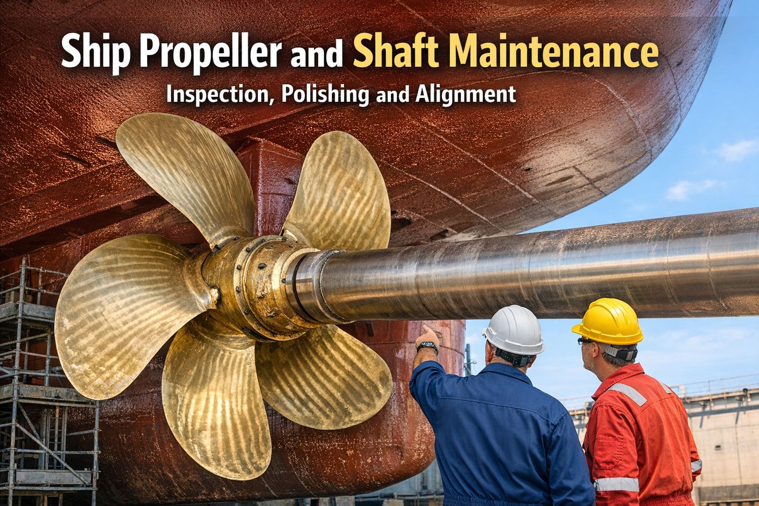
Ship Propeller and Shaft Maintenance: Inspection, Polishing and Alignment
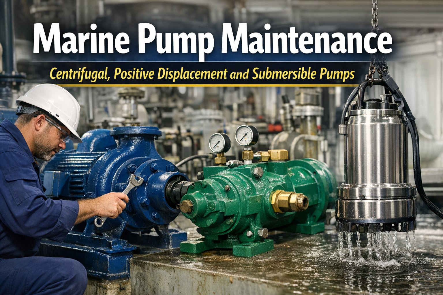
The propeller and shaft line are the mechanical connection between your ship's main engine and the water that propels it — and arguably the hardest-working assembly on any vessel. The tail shaft transmits thousands of horsepower continuously for years between dry dockings, rotating in stern tube bearings lubricated by oil or seawater, sealed against marine ingress by rotary lip seals, and terminating in a propeller that converts rotational power into axial thrust through hydrodynamic forces calculated to tenths of a percentage point. Propeller efficiency directly drives voyage fuel consumption: a fouled or damaged propeller can consume 5-8% more fuel than a clean one — equivalent to tens of thousands of dollars in additional bunker costs per voyage on a typical commercial vessel. Shaft alignment determines bearing life: misalignment causes uneven bearing loads, localised heating, accelerated wear, and eventually catastrophic bearing failure requiring dry dock intervention. Stern tube seal integrity determines whether seawater enters the stern tube (destroying oil-lubricated bearings) or whether lubricating oil escapes to the marine environment (creating pollution claims). For superintendents and engineers, propeller and shaft maintenance sits at the intersection of hydrodynamics, tribology, classification society survey requirements, environmental compliance (EAL lubricants under EPA VGP), and commercial efficiency. The class survey cycle (tail shaft survey timing defined by classification society, typically 5-year intervals with condition monitoring alternatives under modern notations) governs major intervention timing, while underwater propeller polishing between dry dockings maintains fuel efficiency. To see how Marine Inspection digitalises propeller and shaft maintenance records, alignment surveys, and class survey preparation across your fleet, book a Marine Inspection demo.
5-8%
Fuel penalty from fouled propeller
5 Years
Standard tail shaft survey interval
3%
Max shaft diameter reduction allowed by class
2-5 Yrs
Stern tube seal service life
Anatomy of the Shaft Line: What You're Maintaining
The ship's propulsion shafting is a series of connected rotating shafts supported by bearings, each with specific functions and failure modes. Understanding the assembly is essential to diagnosing vibration, wear, and alignment issues. Superintendents who book a Marine Inspection demo can see how the platform catalogues every shaft line component with its specific maintenance requirements.
Forward
Thrust Shaft
Connects main engine crankshaft to the thrust block. The thrust block transfers the propeller's axial thrust to the ship's hull structure, preventing engine bearings from overloading with propulsion force.
Midship
Intermediate Shaft
Connects thrust shaft to tail shaft, maintaining power continuity. Supported by one or more bearings that reduce bending stress. Forged steel with couplings for assembly and maintenance.
Aft
Tail Shaft (Propeller Shaft)
Passes through stern tube and connects directly to propeller. The most critical shaft — subject to classification surveys, withdrawal for inspection, and specific clearance requirements. Houses in stern tube bearings.
Stern
Propeller (Fixed or CPP)
Converts rotational power to axial thrust through hydrodynamic forces. Fixed-pitch or controllable-pitch (CPP) with hydraulic pitch control. Subject to surface inspection, polishing, cavitation damage assessment.
Stern Tube System: Oil-Lubricated vs Water-Lubricated
The stern tube is the metal tube welded to the hull through which the tail shaft passes. It houses bearings supporting the shaft weight and seals preventing seawater ingress. Two lubrication philosophies dominate: oil-lubricated (traditional, pressurised oil bath) and water-lubricated (environmentally friendly, using seawater or freshwater).
Oil-Lubricated Stern Tube
How it works: Stern tube flooded with lubricant oil. Journal bearings operate fully immersed in oil. Header tank maintains oil pressure above external seawater pressure to prevent water ingress.
Seal arrangement: Multiple rotary lip seals (typically 5 seals total across forward and aft packages). Aft seal #1 faces water as dirt excluder. Seal #2 faces water for redundancy. Seals #3 and #4 retain oil. Seal #5 prevents oil leakage into engine room.
Environmental concern: Oil leakage to sea is now regulated under EPA VGP requirements — Environmentally Acceptable Lubricants (EAL) required in US waters. EAL deterioration in aft sealing chamber can compromise ring #3, risking main lubricant system contamination.
Maintenance focus: Header tank oil level, seal condition, lubricant analysis (water content, TAN, wear elements), bearing temperature monitoring.
Water-Lubricated Stern Tube
How it works: Seawater (open loop) or freshwater (closed loop) lubricates bearings. No oil inventory — no oil pollution risk. Lignum vitae or Tufnol-type bearings traditional; modern composite bearings increasingly common.
Seal arrangement: Simpler than oil-lubricated — water naturally present both sides. Stern gland may use packing or modern lip seal designs. Repacking typically required at each bottom survey.
Environmental benefit: Zero oil-to-sea risk. Compatible with EPA VGP requirements. DNV TMON class notations allow unlimited tail shaft withdrawal intervals with condition monitoring.
The tail shaft survey is an independent item from the docking survey, examining propeller condition, stern bush clearance, and seal efficiency. Standard class rules historically required tail shaft withdrawal at 5-year intervals, but modern condition monitoring notations (DNV TMON, similar programmes from other societies) allow extended intervals or even no pre-determined withdrawal based on sensor data.
Pitch control device operation verification; opened if considered necessary
Must be in good working order; seal inspection of hydraulic oil chambers
Guard Ring (Rope Guard)
Visual inspection for condition and secure attachment
Prevents fishing nets and debris fouling shaft; repair/renew if damaged
Modern class notations (DNV TMON, similar) allow extended or unlimited withdrawal intervals based on condition monitoring — wear-down sensors, lubricant analysis, alignment monitoring.
Propeller Damage Assessment & Repair Regions
Propeller blades are divided into three regions (A, B, C) for repair purposes — each region has different structural stress levels, so different damage severities are acceptable. Repair rules per region are defined by classification society and propeller manufacturer specifications.
Region A
Inner Radius / High Stress Zone
Near the hub where bending stresses are highest during operation. Most restrictive repair limits. Cracks here typically unrepairable — require blade replacement or propeller renewal. Any damage in Region A needs urgent expert assessment.
Region B
Mid-Radius Transition
Moderate stress zone. Limited repairs permitted — minor cracks can be machined out within limits. Welding repairs possible but require qualified techniques (MIG/MAG, TIG, laser cladding) and post-weld inspection. Straightening of bent blades performed here under controlled conditions.
Region C
Outer Radius / Tip Zone
Lower bending stress but highest cavitation exposure. More repair latitude — blade tip damage, cavitation erosion, minor edge nicks commonly repaired. Dressing and polishing typically sufficient for minor damage. Larger repairs via welding and re-balancing.
Common Shaft Line Failure Modes
Understanding failure modes is essential for effective preventive maintenance. Six failure patterns account for most shaft line problems on commercial vessels.
1
Shaft Misalignment
Improper alignment between engine, intermediate shaft, and propeller shaft. Causes uneven bearing loads, localised heating, high bearing oil temperatures, accelerated wear. Detection: bearing temperature monitoring, vibration analysis, bearing load measurement. Correction: laser alignment, bearing offsets, re-machining of bearing housings.
2
Stern Tube Seal Failure
Rotary lip seals wear against shaft liner over time. Seal life typically 2-5 years, replaced every dry dock. Seal failure → oil leakage to sea (EPA VGP violation) or water ingress (bearing damage). FKM (Viton) compounds standard for temperature and chemical resistance.
3
Bearing Wear & Damage
White metal wipe, bearing corrosion, groove scoring on shaft liner. Caused by misalignment, contaminated lubricant, lubrication interruption, overloading. Poker gauge wear-down monitoring essential. Severe cases require white metal re-casting and machining offsets.
4
Propeller Damage
Broken blades (>1/3 blade requires port call — possible stern tube damage), bent blades, cracks, cavitation erosion, fallen guard ring. Sudden abnormal stern vibration = immediate stop, assessment, and possible occasional survey.
5
Shaft Liner Damage
Cracks, porosity, slackness at liner extremities. Caused by overheating, thermal cycling, loose copper joints. Slackness next to propeller critical — corrosion exposure. Fully penetrating cracks require liner renewal; surface defects machined within wear limits.
6
Vibration & Imbalance
Out-of-balance propeller, bent shaft, worn couplings, loose mounts. Causes fatigue damage to entire propulsion train. Vibration analysis identifies source. Propeller polishing can correct minor imbalance; bent shafts require straightening (cold or hot methods) by specialists.
Live Platform Walkthrough
See How Marine Inspection Tracks Shaft & Propeller Maintenance
Stern tube seal replacement records, poker gauge wear-down trending, propeller polishing schedules, shaft alignment surveys, tail shaft class survey preparation — all in one platform, accessible across your fleet.
Propeller Polishing: The Fuel Efficiency Investment
Propeller polishing is the most cost-effective fuel efficiency intervention available between dry dockings. A biofouled propeller (barnacles, algae, slime layer) can consume 5-8% additional fuel compared to a clean propeller — equivalent to tens of thousands of dollars per voyage. Underwater propeller polishing by commercial dive teams restores propeller surface smoothness in port, typically in 4-8 hours with no vessel downtime.
01
Pre-Polish Survey
Underwater inspection documents propeller condition before work. Biofouling type and coverage assessed. Any damage (blade nicks, cavitation erosion) photographed and recorded.
02
Fouling Removal
Heavy fouling (barnacles, calcareous growth) removed mechanically. Slime layer and soft fouling removed with abrasive pads. Progressive grit sequence from coarse to fine.
03
Surface Polishing
Progressive polishing restores blade surface smoothness. Target surface roughness typically below 250 microns (Ra) for optimal efficiency. Both pressure and suction faces treated.
04
Damage Dressing
Minor blade edge damage dressed to restore hydrodynamic profile. Cavitation erosion areas evaluated — significant damage requires dry dock repair, not underwater work.
05
Post-Polish Documentation
Video survey after work documents completion. Surface roughness measurements. Records become baseline for next inspection. Submitted to superintendent for records.
06
Performance Verification
Fuel consumption monitored after polish vs baseline. Speed at same power verified. Typical 3-8% fuel consumption reduction immediately after polishing on moderately fouled propellers.
How Marine Inspection Digitalises Propeller & Shaft Management
Propeller and shaft maintenance generates multi-year records critical for class surveys, underwater polishing scheduling, alignment verification, and commercial performance monitoring. Paper records fragmented across crews and superintendents make trend analysis nearly impossible. Here's how Marine Inspection addresses this:
Poker Gauge Trending
Sequential poker gauge readings trended over time reveal bearing wear-down patterns. Essential for tail shaft survey preparation.
Lubricant test results (water content, TAN, wear elements) trended over time. Early warning for seal or bearing deterioration before class survey.
Class Survey Scheduling
Tail shaft survey intervals tracked against class requirements (standard or TMON-style condition monitoring). Automated reminders prevent survey deadline surprises.
Vibration Monitoring Logs
Propulsion train vibration readings captured over time. Spikes investigated before they become failures. Fleet-wide baseline establishes normal vs abnormal for each vessel.
EAL Compliance Records
Environmentally Acceptable Lubricant use documented for EPA VGP compliance. Sampling schedules, test results, vendor certifications all retained digitally.
Preventive Maintenance & Monitoring Schedule
Daily
Log stern tube oil temperatures (forward and aft bearings). Check header tank level. Monitor shaft vibration indicators if fitted. Verify oil flow/pressure on oil-lubricated systems.
Weekly
Inspect stern tube oil sight glass for discoloration or water contamination. Check gland drip rate on water-lubricated systems. Verify thrust bearing temperature readings.
Monthly
Stern tube oil sample for laboratory analysis (water content, TAN, wear elements). Check bearing wear-down via remote sensors if fitted. Vibration monitoring survey.
Quarterly
Poker gauge reading (where accessible). EAL system condition check in aft sealing chamber (for oil-lubricated stern tubes with EAL). Coupling bolt torque verification.
Annually
Detailed alignment check (class survey requirement for some notations). Comprehensive vibration analysis. Thrust bearing inspection. Intermediate shaft bearing condition assessment.
Between Dockings
Underwater propeller polishing every 6-12 months depending on trading pattern and biofouling rate. Underwater inspection by qualified diving company with video documentation.
Dry Dock
Propeller inspection and polishing. Stern tube seal replacement. Shaft liner inspection. Tail shaft withdrawal if required by class cycle. Bearing clearance measurements.
Tail Shaft Survey
Major class event — shaft withdrawal or condition monitoring verification per class notation. NDT of shaft. Complete bearing inspection. Seal renewal. Alignment verification.
Shaft Alignment: The Discipline That Determines Bearing Life
Shaft alignment determines whether bearings last decades or fail within months. Modern class rules (DNV Pt.4 Ch.2 Sec.4) require analytical verification of bending moments and deflection curves to ensure even load distribution. Double-sloped aft bearing designs accommodate the natural deflection of shaft under propeller weight.
Method 1
Gap & Sag Measurement (Traditional)
Feeler gauges at coupling flanges measure gap (axial) and sag (offset). Simple method, limited accuracy. Requires shaft removed from bearings or lifted. Can give false confidence — shafts can appear aligned at couplings while overall alignment is out.
Method 2
Laser Alignment Systems
Modern standard for new installations and major realignments. Accurate to fractions of a millimeter. Measures misalignment in multiple planes simultaneously. Used during dry dock alignment verification and after shaft modifications.
Method 3
Bearing Reaction Measurement
Hydraulic jacks measure actual bearing reactions under static shaft load. Compares measured values to calculated values from bending moment analysis. Gold standard for verifying alignment on large installations.
Method 4
Strain Gauge Analysis
Strain gauges bonded to shaft measure actual bending stress under operation. Reveals dynamic alignment issues that static methods miss. Used for troubleshooting vibration problems and verification after major repairs.
Conclusion
Ship propeller and shaft maintenance is the engine room discipline with the longest maintenance cycles but the most consequential outcomes — tail shaft surveys every 5 years (or extended under condition monitoring notations), stern tube seal replacements every dry dock, propeller polishing every 6-12 months between dockings, and continuous monitoring of alignment, vibration, and lubricant condition. The stern tube system (oil-lubricated with 5-seal packages or water-lubricated with modern composite bearings) requires discipline across lubricant analysis, seal replacement, bearing wear-down trending, and EPA VGP compliance for EAL lubricants. Propeller management combines class-defined repair regions (A, B, C with different damage acceptability), underwater polishing for 5-8% fuel efficiency gains between dockings, and blade damage assessment protocols. Shaft alignment determines bearing life — traditional gap/sag measurements supplemented by laser alignment, bearing reaction measurement, and strain gauge analysis on modern installations. The superintendents and engineers who deliver reliable propulsion performance across decades of service are those whose maintenance programmes are systematic, digitalised, and trend-analysed. To see how Marine Inspection transforms propeller and shaft management across your fleet, book a live demo today.
Frequently Asked Questions
FAQ 01
How often should a tail shaft be surveyed?
Standard classification society rules historically require tail shaft survey every 5 years including shaft withdrawal for inspection. Modern class notations (DNV TMON, similar programmes from other societies) allow extended or even unlimited intervals based on condition monitoring — wear-down sensors, lubricant analysis, alignment monitoring, and stringent seal system requirements. The tail shaft survey is an independent item from the docking survey, examining propeller condition, stern bush clearance, oil gland efficiency, and CPP operation where fitted. Interval extensions require approval under specific class notations and compliance with design and operational criteria.
FAQ 02
How much fuel does propeller polishing save?
A biofouled propeller can consume 5-8% more fuel than a clean propeller. Underwater propeller polishing by commercial dive teams typically delivers 3-8% fuel consumption reduction immediately after polishing on moderately fouled propellers — the variation depends on pre-polish fouling severity and polishing quality. The investment pays back rapidly: polishing costs a few thousand dollars per operation versus tens of thousands of dollars in additional bunker costs per voyage. Recommended frequency is every 6-12 months between dry dockings, though trading pattern (warm water areas like Middle East and Asia promote faster biofouling) affects optimal interval.
FAQ 03
What causes stern tube seal failure?
Stern tube seal failure causes include: (1) Normal wear — FKM lip seals wear against shaft liner over 2-5 years typical service life. (2) Fishing line/rope entanglement damaging the aft seal package. (3) Shaft liner corrosion creating abrasive surface. (4) Oil deterioration in aft sealing chamber — particularly a concern with EAL lubricants in oil-lubricated systems where EAL in the sealing chamber can deteriorate, compromising seal ring #3. (5) Thermal damage from lubrication interruption. (6) Shaft misalignment causing uneven seal contact pressure. Seal failure → oil leakage to sea (EPA VGP violation) or water ingress (bearing damage). Seals are typically replaced every dry dock regardless of condition as preventive measure.
FAQ 04
What maximum wear is allowed on a propeller shaft?
Classification society rules allow up to 3% reduction in shaft rule diameter through machining or grinding — corresponding to approximately 10% decrease in torsion strength. Below this limit, surface defects can be machined out. Above this limit, shaft renewal is required. Bearing journal polishing is routine during surveys to remove minor scoring. Fully penetrating cracks in shaft liners require liner renewal regardless of remaining thickness. Surface cracks detected by magnetic particle inspection (preferred) or dye penetrant can be machined provided liner thickness remains within wear limits. Crack depth verified by ultrasonic testing before machining proceeds.
FAQ 05
What's the difference between oil-lubricated and water-lubricated stern tubes?
Oil-lubricated stern tubes flood the bearing chamber with pressurised oil — traditional design with excellent bearing life but environmental risk from oil leakage to sea. Uses multiple rotary lip seals (typically 5 seals across forward and aft packages) with EAL (Environmentally Acceptable Lubricants) required in US waters under EPA VGP. Water-lubricated stern tubes use seawater (open loop) or freshwater (closed loop) to lubricate bearings — traditional lignum vitae or modern composite bearings. Zero oil pollution risk; compatible with environmental regulations. DNV TMON class notations allow unlimited tail shaft withdrawal intervals with condition monitoring on water-lubricated systems. Water-lubricated systems require stringent design, alignment, and monitoring standards.
Book Your Live Demo
Digitalise Your Propulsion Maintenance Programme
30 minutes with our team. See how Marine Inspection transforms poker gauge trending, stern tube oil analysis, underwater polishing records, class survey scheduling, and shaft alignment surveys into a single fleet-wide digital platform built for superintendents and engineers.