Mooring operations remain among the most dangerous routine activities on any vessel — nearly all mooring injuries result from mooring line failures, and the snap-back zone from a parting high-strength synthetic line can be lethal. OCIMF's Mooring Equipment Guidelines Fourth Edition (MEG4), IMO MSC.1/Circ.1619 (design of mooring arrangements), and MSC.1/Circ.1620 (inspection and maintenance of mooring equipment including lines) together define the modern regulatory framework that deck officers and bosuns must work within. For anchoring, the picture is equally critical: windlasses are typically designed to lift a maximum of the anchor weight plus three free-hanging shackles of chain cable (82.5-100 metres depending on class requirements) — they are not designed to break out the anchor from the seabed, and the majority of anchoring system failures trace back to insufficient understanding of capability or lack of maintenance. Anchor chain, mooring ropes (synthetic and wire), winches, windlasses, fairleads, bollards, chain stoppers, and chain lockers — each component has specific inspection criteria, maintenance requirements, and discard parameters that determine whether the mooring and anchoring system performs reliably when crew safety depends on it. For deck officers and bosuns building systematic mooring and anchoring maintenance programmes, including Mooring System Management Plans (MSMP) and Line Management Plans (LMP) required under current regulations, Marine Inspection provides the digital platform that tracks every component's condition and certification. Book a Marine Inspection demo to see how.

Regulatory Framework: What Governs Your Mooring & Anchoring Equipment
OCIMF MEG4
Industry standard for safe mooring of tankers and gas carriers. Defines MBLSD, LDBF, WLL terminology. Requires Mooring System Management Plan (MSMP) and Line Management Plan (LMP). VIQ7 SIRE inspection references MEG4 compliance.
IMO MSC.1/Circ.1619
Guidelines on mooring arrangement design and equipment selection for safe mooring. Applicable to ships built after January 1, 2024. Defines Ship Design MBL as core parameter.
IMO MSC.1/Circ.1620
Guidelines for inspection and maintenance of mooring equipment including lines. Applicable to all ships. Defines criteria for identifying worn-out lines before failure.
Classification Society Rules
Chain grade and size, anchor weight, windlass capacity, chain stopper requirements, brake holding capacity. Periodic anchor chain ranging and gauging during class surveys.

Anchoring System Components and Maintenance

The anchoring system is exposed to the harshest marine environment on the vessel — weather deck, seawater immersion, dynamic loading from anchor recovery, and extended periods without use between anchorings. Systematic maintenance prevents the failures that OCIMF data shows most commonly trace to lack of maintenance. Book a Marine Inspection demo to see component-level tracking for every anchoring element.

Windlass

Function: Heaves anchor and chain from depths of 82.5-100m. Designed for anchor + 3 shackles free-hanging weight. Not designed to break anchor from seabed.

Types: Hydraulic motor-driven (most common on large vessels) or electric motor-driven. Cable lifter (wildcat) engages chain links; separate gearing for chain sizes above 50mm diameter.

Maintenance: Hydraulic motor service (seals, bearings, relief valve). Brake band condition and adjustment (minimum 45% of chain rule breaking load with chain stopper; 80% without). Cable lifter wear inspection. Clutch mechanism. Stripper bar alignment. Foundation bolts. Grease points.

Anchor Chain

Function: Connects anchor to vessel via chain locker. Graded by steel quality (Grade 2, Grade 3). Length in shackles (1 shackle = 27.5m). Joining shackles, common links, enlarged links, swivel.

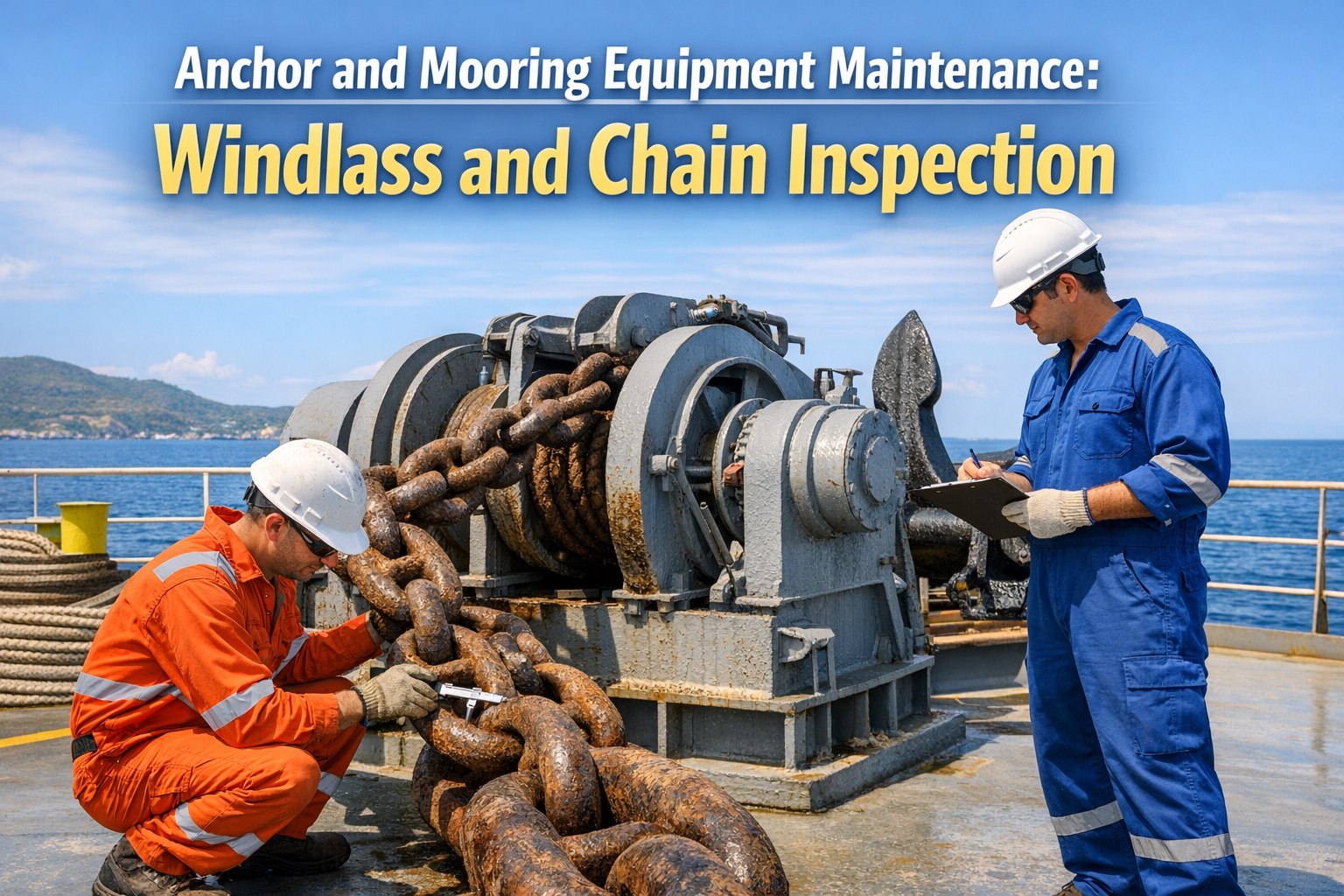
Inspection: Ranging: entire chain ranged on deck/quay for visual inspection during dry dock or class survey. Gauging: measure link diameter at wear points — maximum 12% reduction allowed (class rule). Check for cracks, distortion, corrosion pitting. Joining shackle condition.

Maintenance: Chain locker cleaning. Bitter end securing inspection. Chain marking verification. Lubrication of joining shackles.

Chain Stopper

Function: Secures chain when anchor is stowed, taking load off windlass brake. Roller stoppers (most common) or guillotine type. Guide roller reduces friction.

Maintenance: Roller condition and bearing lubrication. Locking mechanism function test. Structural condition of stopper body and deck attachments. Foundation bolt torque.

Anchor Lashing

Function: Secures anchor tightly in stowed position. Wire or chain sling through chain link, secured via bottlescrew to deck structure. Loose anchor can penetrate hull.

Maintenance: Lashing wire/chain condition. Bottlescrew thread condition and lubrication. Securing points structural integrity. Tightness verification before every voyage.

Mooring Equipment: Lines, Winches, and Fittings

Mooring Equipment Inventory & Maintenance Requirements
Equipment Function Key Maintenance Inspection Criteria
Mooring WinchHauls in/pays out mooring lines during berthingHydraulic motor service, brake adjustment (holding load per OCIMF), drum condition, warping head wear, control systemBrake holding capacity test; split-drum: min 80% of rope breaking strength
Synthetic Mooring LinesPrimary mooring lines (HMPE, nylon, polypropylene, polyester)Monthly visual inspection entire length; open strands for internal wear check; diameter measurement at stress points; retirement per maker's criteriaCuts, abrasions, twists, stiffness (heat damage), diameter below threshold = discard
Wire Mooring RopesHigher-strength mooring with less stretchWire rope inspection per ISO 4309 (broken wires, diameter reduction, corrosion). Quarterly EAL lubrication to penetrate core. Wire rope dresser for even coverage.Broken wire count, diameter reduction >7-10%, corrosion, deformation, kinks
Mooring TailsEnergy absorption between wire/HMSF lines and vessel fittingsTail Design Break Force (TDBF) 125-130% of Ship Design MBL per MEG4. Inspect connections, splices, chafe protection. Condition monitor per LMP.Proper connection method, correct length, wear at chafe points, retirement criteria
Fairleads / Pedestal RollersGuide mooring lines from winch to vessel sideRoller bearing condition and lubrication. Structural integrity of foundation and mounting. Wear on roller surfaces and cheek plates.Free rotation, no excessive play, foundation bolt integrity, no cracks or deformation
Bollards / BittsSecure mooring lines to vessel deckFoundation and deck structure inspection. Coating condition. Rope contact surface condition for sharp edges.Structural integrity, foundation weld condition, deck reinforcement
Chain Stopper (Mooring)Holds mooring chain or wire in secured positionLocking mechanism, roller condition, structural body inspection, foundation boltsFree operation under load, no structural cracks, foundation secure
Emergency Towing ArrangementsPre-rigged towline for emergency assistanceCondition of pennant wire/line, chafe chain, fairlead, strongpoint. Annual deployment drill.Ready for deployment within time required by SOLAS; condition of all components
MEG4 key terms: Ship Design MBL (MBLSD) — core design parameter. Line Design Break Force (LDBF) = 100-105% of MBLSD. Tail Design Break Force (TDBF) = 125-130% of MBLSD. Nylon lines break-tested wet.

Anchor Chain Inspection: Ranging and Gauging

Anchor chain inspection is a class survey requirement that verifies chain integrity after years of seabed contact, corrosion exposure, and dynamic loading. The process involves ranging (laying out) the entire chain length for visual and dimensional inspection.

Anchor Chain Inspection Criteria
Inspection Item Method Acceptance / Rejection Criteria
Link DiameterCaliper measurement at wear points (crown and sides)Max 12% diameter reduction from original — beyond this, shackle/links renewed
Link DistortionVisual inspection for bent, twisted, or elongated linksAny link showing permanent deformation — replace
CracksVisual + magnetic particle inspection (MPI) on suspect areasAny crack in weld or parent material — replace affected links
CorrosionVisual assessment; measurement where pitting evidentDeep pitting reducing effective section — replace. General wastage assessed by diameter measurement
Stud ConditionVisual inspection for loose, broken, or missing studsLoose or missing studs — re-weld or replace. Studs prevent chain knotting in locker
Joining ShacklesDisassemble joining shackles, inspect pin, taper, lead pellet sealPin wear, taper fit, lead pellet intact. Replace components as required
Swivel & Swivel ShackleFunctional test and visualFree rotation without binding. No cracks. Pin wear within limits
Chain MarkingsVerify painted markings correspond to correct shackle countRepaint/re-mark to ensure accurate shackle identification during operations
Chain ranging typically performed during dry dock or alongside with quay space. Entire chain laid out for inspection. Photographs document condition for class records.

Mooring Safety: Snap-Back Zones and Crew Protection

Nearly all mooring injuries result from mooring line failures — and the energy released when a high-strength synthetic line parts under tension creates lethal snap-back zones. MEG4 places significant emphasis on human factors and snap-back zone management. Sign up for Marine Inspection to document snap-back zone assessments and crew briefing records.

1
Snap-Back Zone Identification
Mark snap-back zones on deck with high-visibility paint or signage. Assessment based on mooring line type, layout, and potential failure trajectory. MEG4 requires snap-back zone assessment as part of MSMP.
2
Personnel Exclusion During Tension
No personnel in snap-back zone when lines are under tension. Clear communication between bridge and mooring stations. Crew briefing before every mooring operation.
3
Line Condition Monitoring
Lines that have exceeded Working Load Limit (WLL) require risk assessment per MSMP. Wear zone assessment, detailed inspection, and potential testing of samples from loaded lines.
4
Winch Brake Calibration
Winch brakes designed to render (slip) before line reaches breaking load — protecting both the line and deck fittings. Brake setting calibrated to vessel's specific mooring line strength.
5
MSMP & LMP Documentation
Mooring System Management Plan and Line Management Plan required. Document mooring hours per line, inspection records, manufacturer guidelines, wear zone management, and retirement criteria.
6
SIRE VIQ7 Readiness
OCIMF VIQ7 includes MEG4-referenced questions: certificates for all lines, MSMP availability, LMP implementation, line/tail condition, correct connections. Digital records enable instant verification.

How Marine Inspection Digitalises Mooring & Anchoring Management


Mooring Line Inventory & Certificates: Digital register of every mooring line and tail with type, LDBF, manufacturer certificate, installation date, mooring hours logged, inspection history, and retirement status.

Line Management Plan (LMP): Digital LMP tracking mooring hours per line position, wear zone assessments, inspection records, and manufacturer retirement criteria — the documentation SIRE VIQ7 verifies.

Chain Ranging Records: Anchor chain inspection data with link diameter measurements, photograph evidence, shackle condition, and trending against previous surveys for progressive wear monitoring.

Windlass & Winch Maintenance: Running hour-based PM scheduling for hydraulic motors, brake adjustment records, cable lifter wear measurements, and foundation bolt torque checks.

Snap-Back Zone Documentation: Assessment records, deck marking verification, crew briefing logs with participation evidence — supporting both MSMP compliance and operational safety culture.

Class Survey Preparation: Chain gauging records, equipment certificates, inspection histories, and test records accessible instantly during class surveys, PSC inspections, and SIRE vettings.
See It Live
Book Your Marine Inspection Demo
30 minutes. See mooring line tracking, chain inspection records, windlass PM scheduling, snap-back zone documentation, and SIRE VIQ7-ready mooring evidence across your fleet.

Preventive Maintenance Schedule

Before Each Operation
Visual check all mooring lines for damage; verify winch/windlass brake function; check fairlead roller rotation; confirm communication between bridge and mooring stations; crew briefing on snap-back zones.
Monthly
Full-length mooring line inspection (open strands for internal wear on synthetics). Wire rope inspection per ISO 4309. Diameter measurement at stress points. Windlass/winch grease points. Chain stopper function test.
Quarterly
Wire rope lubrication (EAL-compatible marine lubricant). Mooring winch brake holding test. Hydraulic system pressure verification. Fairlead bearing condition. Bollard/bitt foundation inspection.
Semi-Annual
Windlass hydraulic motor service. Clutch mechanism inspection. Cable lifter wear measurement. Chain stopper roller bearing service. Emergency towing arrangement deployment drill.
Annual
Comprehensive windlass overhaul (brake band, gearbox, motor). Mooring line age and condition review against LMP. Anchor lashing condition. Chain locker inspection. Control system function verification.
Dry Dock / Class Survey
Anchor chain ranging and gauging (entire length). Chain locker cleaning and inspection. Anchor inspection. Windlass foundation structural inspection. Chain pipe and spurling pipe condition. Hawse pipe coating.

Conclusion

Anchor and mooring equipment maintenance protects crew from the mooring line snap-back injuries that remain among maritime's most serious occupational hazards, and ensures the anchoring system performs reliably when vessel safety depends on it. The regulatory framework — OCIMF MEG4, IMO MSC.1/Circ.1619 and 1620, and classification society rules — defines specific requirements for Mooring System Management Plans (MSMP), Line Management Plans (LMP), chain gauging (max 12% diameter reduction), brake calibration (min 45-80% of chain breaking load), mooring line condition monitoring with retirement criteria, and snap-back zone assessment. Windlass maintenance combines hydraulic motor servicing, brake band condition, cable lifter wear measurement, and structural foundation inspection. Mooring line management follows MEG4 terminology: Ship Design MBL (core parameter), Line Design Break Force (100-105% of MBLSD), and Tail Design Break Force (125-130% of MBLSD). The deck officers and bosuns who deliver reliable, safe mooring operations are those whose maintenance programmes are systematic, documented, and SIRE VIQ7-ready. Marine Inspection provides the digital platform that turns mooring and anchoring maintenance from paper-based liability into systematic operational discipline — book a live demo today.

Frequently Asked Questions

FAQ 01
What is OCIMF MEG4 and does it apply to my vessel?
OCIMF MEG4 (Mooring Equipment Guidelines Fourth Edition) is the industry standard for safe mooring, primarily targeting tankers and gas carriers. However, its principles are increasingly adopted across all vessel types. MEG4 requires Mooring System Management Plans (MSMP) and Line Management Plans (LMP), introduces standardised terminology (Ship Design MBL, LDBF, WLL), and addresses human factors including snap-back zone management. For ships built after January 1, 2024, IMO MSC.1/Circ.1619 (design guidelines) and MSC.1/Circ.1620 (inspection and maintenance guidelines) apply — these align with MEG4 terminology. The OCIMF SIRE Vessel Inspection Questionnaire (VIQ7) includes MEG4-referenced questions, making compliance directly relevant to tanker and gas carrier vetting outcomes.
FAQ 02
How is anchor chain inspected during surveys?
Anchor chain inspection involves ranging (laying out the entire chain length on deck or quay) and gauging (measuring link diameter at wear points using calipers). Maximum allowable diameter reduction is 12% from original — beyond this, links or shackles must be renewed. Inspection covers: link diameter measurement, visual check for distortion, cracks (MPI on suspect areas), corrosion pitting assessment, stud condition (loose or missing studs re-welded), joining shackle disassembly (pin wear, taper fit, lead pellet integrity), swivel function, and chain marking accuracy. The inspection is a class survey requirement, typically performed during dry dock. Photographs document condition for class records. Progressive wear trending across surveys reveals chain sections approaching discard limits.
FAQ 03
What windlass brake holding capacity is required?
Windlass brake holding capacity depends on whether a chain stopper is fitted: With chain stopper fitted, the windlass brake must hold at least 45% of the chain's rule breaking load — the chain stopper takes the primary holding load. Without chain stopper, the windlass brake capacity must be increased to at least 80% of the chain's rule breaking load — the brake becomes the primary holding mechanism. For mooring winches (split-drum type), brake holding load should be minimum 80% of the mooring rope breaking strength. Brake adjustment and testing is a critical maintenance activity — under-tensioned brakes allow chain or rope to run; over-tensioned brakes prevent the designed rendering (slipping) that protects deck fittings and hull structure from excessive loads.
FAQ 04
When should mooring lines be retired?
Mooring line retirement criteria per MEG4 and MSC.1/Circ.1620 include: (1) Diameter reduction below manufacturer's specified threshold at any measurement point. (2) External damage — cuts, abrasion, twists that compromise structural integrity. (3) Internal wear — opening strands reveals core damage, broken yarns, or contamination. (4) Stiffness indicating heat damage (from winch brake slipping under load). (5) Age — manufacturer's recommended service life exceeded. (6) Exposure to loads exceeding Working Load Limit (WLL) without subsequent assessment. (7) Chemical or UV degradation. Lines must be documented in the Line Management Plan with mooring hours, inspection records, and condition assessments. Lines meeting any discard criterion must be retired from service — do not downgrade to less critical positions.
FAQ 05
What is a Mooring System Management Plan?
The Mooring System Management Plan (MSMP) is a vessel-specific document required under MEG4 and IMO MSC.1/Circ.1619. It covers: (1) Description of the vessel's mooring system design including MBLSD, mooring arrangement, and equipment capacities. (2) Snap-back zone assessment and crew protection measures. (3) Mooring procedures for various berth configurations. (4) Line Management Plan (LMP) documenting mooring line inventory, condition monitoring, wear zone assessment, inspection schedule, and retirement criteria. (5) Risk management procedures for lines that have exceeded WLL. (6) Crew training and familiarisation requirements. (7) Documentation and record-keeping protocols. The MSMP is verified during SIRE inspections (VIQ7), flag state audits, and port state control. Digital implementation ensures the document is living and updated, not a one-time paper exercise.
Book Your Live Demo
Digitalise Mooring & Anchoring Maintenance Across Your Fleet
30 minutes with our team. See how Marine Inspection tracks mooring line inventories, chain inspection records, windlass PM scheduling, snap-back zone assessments, MSMP/LMP documentation, and SIRE VIQ7-ready evidence — purpose-built for deck officers, bosuns, and superintendents managing mooring safety.
12%
Max chain diameter reduction before renewal
45-80%
Windlass brake holding capacity
MEG4
OCIMF industry standard for safe mooring
VIQ7
SIRE inspection references MEG4