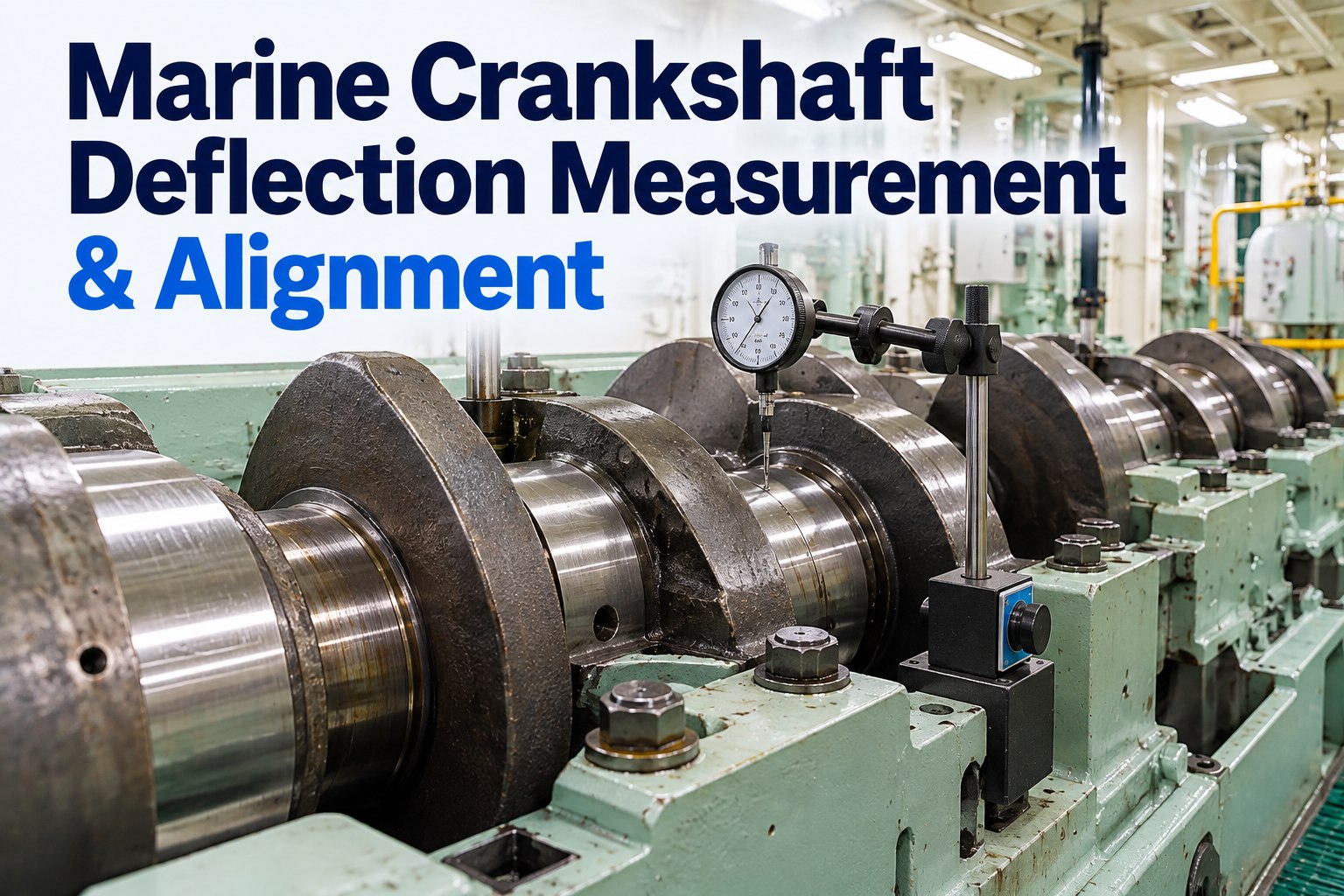
A crankshaft is supposed to be straight, and it never quite is. Main bearings wear at different rates, chocks and holding-down bolts relax, the bedplate ages, and the hull itself bends around the engine as the ship loads, discharges and works in a seaway. The result is a shaft that runs with a slight curve, and a curve means the webs open and close as each crank turns. That flexing is what eventually cracks a web or wipes a bearing. Deflection measurement is how you see it before it becomes damage: a dial gauge between the webs, five readings around one revolution, and a set of numbers that can be compared with the maker's limits and, more usefully, with the last set taken under the same conditions. This guide covers where to measure and in what order, how to run the job so the readings mean something, how to work out vertical and horizontal deflection, how to read the patterns, and what to do when a unit goes out of limits. Every limit comes from the engine maker's manual, and readings should always be compared with your own previous set. To keep readings, draughts and conditions with the engine record rather than in a notebook, try Marine Inspection free.
Alignment and bearings
A deflection reading is only as good as the conditions you record with it
Same gauge point, same direction of turning, same loading condition, same crew method. Change any of those and the comparison with the last set is worthless.
Readings taken at different draughts or loading conditions cannot be compared with each other.
What deflections actually tell you
The gauge measures the distance between the webs changing as the crank turns. If the journal centres were in a perfect line, that distance would not change at all and every reading would be zero. Any change means the shaft is being bent by something.
Main bearing wearUneven wear along the shaft lets some journals sit lower than others, which is the most common cause of a growing vertical deflection.
Bedplate and chocksSlack holding-down bolts, deteriorated chocks or a distorted bedplate move the bearing housings themselves.
Hull deflectionThe hull bends with loading, trim, hog and sag, and the engine bends with it. This is why loading condition is part of the reading.
Alignment of the driven endStern tube bearing wear, shaft alignment and thrust arrangements show up most strongly at the units nearest the flywheel.
Damage eventsGrounding, contact, heavy weather or a bearing failure are all reasons to measure before returning to full power.
Fatigue riskA shaft that flexes every revolution accumulates fatigue in the webs and fillets, which is the failure nobody recovers from at sea.
The five measurement positions
Readings would ideally be taken at top, bottom, port and starboard. The bottom position is blocked by the connecting rod, so two readings are taken either side of bottom dead centre and averaged. That gives five positions in one revolution.
B1First reading, taken just after the crank pin has passed bottom dead centre, commonly around 10 to 15 degrees past, with the gauge set to zero here
PPort horizontal position
TTop dead centre
SStarboard horizontal position, often read with a mirror on a flexible arm
B2Last reading, just before the connecting rod would foul the gauge on the way back to bottom dead centre
Then calculateB is the average of B1 and B2. Vertical deflection is T minus B. Horizontal deflection is S minus P.
Running the job properly
The mechanics are simple. The discipline is what makes the numbers usable a year later.
1
Prepare the engineTurning gear engaged, indicator cocks open, permits in place, and the ship afloat. Agree with the bridge that the engine will be turned.
2
Choose a starting unitThere is no need to start at number one. Start with the unit closest to the position where the gauge can be fitted, then work through the rest consistently.
3
Mark the gauge pointUse the same punch marks on the webs every time. A gauge sitting a few millimetres off centre gives a different answer.
4
Zero at the first bottom positionInsert the gauge on the shaft centreline just past bottom dead centre and set it to zero. Every other reading is relative to that point.
5
Turn one way onlyTurn continuously in one direction through P, T and S to the second bottom position. Reversing introduces backlash and false readings.
6
Record signs carefullyA positive reading means the webs are closing, a negative one means they are opening. The sign is what tells you the shape of the curve.
7
Repeat for every unitSame method, same direction, same conditions, and note anything unusual such as a stiff spot while turning.
8
Compute and compareWork out T minus B and S minus P for each unit, compare with the maker's limits, then compare with the last set.
Small enginesOn engines below roughly 250 mm bore, taking deflections is often not practical, and condition is judged by other means. Check what your manual expects before planning the job.
Worked example: one six-cylinder engine
All values in millimetres, with an example maker's limit of 0.12 mm on both planes. Your own limit will differ, and some makers give separate figures for the end units.
Unit
B1
P
T
S
B2
B avg
Vertical T−B
Horizontal S−P
Status
1
0.00
−0.01
−0.02
0.01
0.00
0.00
−0.02
0.02
Normal
2
0.00
−0.02
−0.05
0.01
0.00
0.00
−0.05
0.03
Normal
3
0.00
−0.03
−0.08
0.02
0.00
0.00
−0.08
0.05
Watch
4
0.00
−0.05
−0.13
0.04
0.00
0.00
−0.13
0.09
Over limit
5
0.00
−0.02
−0.07
0.02
0.00
0.00
−0.07
0.04
Watch
6
0.00
0.01
0.03
0.03
0.00
0.00
0.03
0.02
Normal
Vertical deflection by unit, against the example limit band
The shape matters as much as the single value. Here the curve dips towards the middle and recovers, which is the classic picture of the shaft sagging around units three to five, with unit four outside the limit.
Horizontal deflection by unit, as a share of the example limit
Unit 1
0.02
Unit 2
0.03
Unit 3
0.05
Unit 4
0.09
Unit 5
0.04
Unit 6
0.02
Bar length is the reading as a percentage of the 0.12 mm example limit. Horizontal deflection rising with vertical on the same unit usually points at the bearing rather than at the hull.
Reading the patterns
Individual numbers tell you whether you are inside the limit. The pattern across the engine tells you what to look at.
Webs closing at top, opening at bottomPositive at top dead centre and negative near bottom is the classic picture of a shaft hogging, with the centre journals sitting high relative to the ends.
Webs opening at topThe opposite sense indicates sagging, with the centre of the shaft low. On a marine installation this often follows bearing wear in the middle of the engine.
One unit standing outA single unit well away from its neighbours points at that bearing: wear, a damaged shell, or a loose or broken chock under that housing.
Rising towards the flywheel endSuspect the aftermost bearings, the thrust arrangement, shaft alignment and stern tube wear rather than the engine itself.
Large horizontal readingsHorizontal deflection is less affected by hull bending, so a significant S minus P value usually means the bearing or the housing rather than loading condition.
Sudden change between setsA jump since the last measurement is more significant than a steady value near the limit. Investigate before the next voyage.
When a unit is out of limits
An out-of-limit reading is a finding, not a diagnosis. Confirm it before acting, then work outwards from the most likely cause.
1
Repeat the measurementSame conditions, same gauge point, same direction. Confirm the reading before anything is dismantled.
2
Check the conditionsDraught, trim and loading. Repeating in the same condition as the previous set often explains part of the difference.
3
Inspect the bearingClearance by bridge gauge or feeler, oil supply, and the shell condition if opened. Look for wiping, debris and temperature history.
4
Check the seatingHolding-down bolt tightness, chock condition, and any sign of movement, fretting or oil tracking under the bedplate.
5
Look at the bedplateCracks in the transverse girders and around the bearing housings, particularly on older engines with a history of deflection movement.
6
Consider the shaftingStern tube bearing wear and shaft alignment where the readings rise towards the aft end. This may need alignment measurement rather than engine work.
7
Involve class and the makerWhere readings are outside the limit, class attendance or maker advice is usually required before returning to full power. Record what was agreed.
8
Re-measure after correctionA new set of readings after the repair proves the fix and becomes the new baseline.
How often to measure
Frequency comes from the planned maintenance system, the maker's manual and the class survey arrangement, but the triggers below are widely used.
On the planned intervalAs set by the maintenance system, and normally in the same loading condition each time so the sets can be compared.
At engine surveyDeflections are a standard part of a machinery survey and are usually asked for by the surveyor.
After grounding or contactAny event that might have bent the hull or the shafting, including heavy weather damage.
After bearing workWhenever a main bearing has been renewed, adjusted or investigated.
Before and after drydockingThe ship sits differently in dock, so readings afloat before and after are the meaningful pair.
On any symptomBearing temperature alarms, oil mist detection, unusual noise, or metal in the filters or on the magnets.
Common mistakes that spoil the readings
Gauge not at the marked point on the web, so the lever arm is different from last time
Engine turned back and forth, introducing backlash into the readings
Readings taken with the ship in dock, or at a different draught from the previous set
Signs recorded inconsistently, so an opening reading looks like a closing one
Hot engine one time, cold the next, with no note of which
Only the calculated values kept, so nobody can re-check the arithmetic later
Turning gear left engaged or the indicator cocks left shut afterwards
No photograph of the gauge in position, so the method cannot be repeated
Keep the raw readings, not just the answerRecord all five positions per unit with the draughts, loading condition and running hours, and the next set can be compared properly instead of argued about.
Because the connecting rod blocks the gauge at bottom dead centre. Two readings are taken either side of the bottom position and averaged to give the bottom value.
How is deflection calculated?
Vertical deflection is the top reading minus the average of the two bottom readings. Horizontal deflection is the starboard reading minus the port reading. Both are compared with the maker's limits.
Does the ship have to be afloat?
Yes. The hull shape in dock is not the shape at sea, and readings taken in dock cannot be compared with readings taken afloat. Record the draughts, and ideally repeat in the same loading condition each time.
What limit applies to our engine?
Only the one in your manual. Published examples, such as a maximum difference of 0.12 mm between top and bottom positions, are illustrative. Some makers also set different limits for the end units.
What does a positive reading mean?
That the webs are closing as the crank turns to that position. A negative reading means they are opening. The signs across the units describe whether the shaft is hogging or sagging.
What records should be kept?
All five raw readings per unit, the calculated values, the conditions, the gauge used, and the previous set for comparison. See our main engine overhaul guide and lube oil analysis guide, since bearing problems usually show in both.
Same method, same conditions, every time
Marine Inspection records all five readings per unit with the draughts, loading condition and running hours, calculates nothing you cannot check, and keeps the last set alongside for comparison.