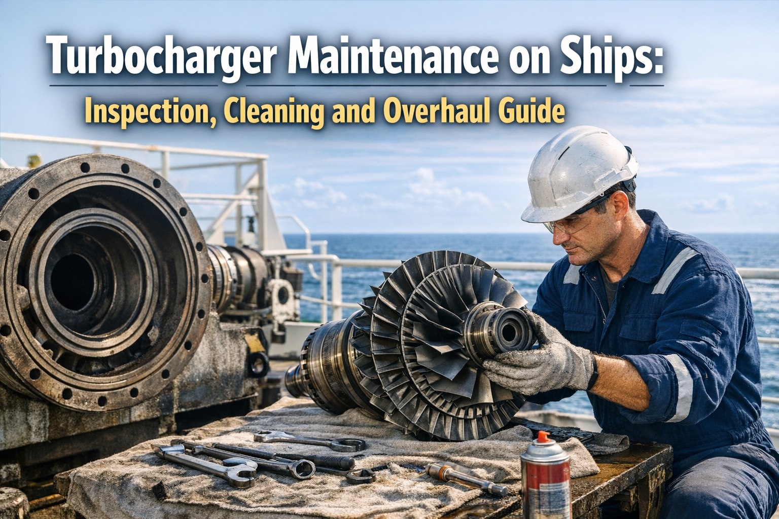
Turbocharger Maintenance on Ships: Inspection, Cleaning and Overhaul Guide
The turbocharger is the force multiplier at the heart of every modern marine diesel engine — using waste exhaust gas energy to compress intake air, enabling more fuel to burn per cycle and producing 30-50% more power from the same cylinder displacement without any additional fuel input. A well-maintained turbocharger delivers optimal scavenge air pressure, complete combustion, clean exhaust, and maximum fuel efficiency. A poorly maintained one triggers a cascade of engine problems: surging that damages blades and bearings, reduced scavenge pressure that causes incomplete combustion and black smoke, elevated exhaust temperatures that accelerate thermal degradation of cylinder components, and ultimately the catastrophic failure scenarios — blade liberation, bearing seizure, or uptake fire from unburned fuel and oil deposits ignited by excessive exhaust temperatures. With IMO CII regulations making engine efficiency a direct commercial metric and fuel costs representing 50-60% of vessel operating expenses, turbocharger efficiency is no longer just an engineering concern — a well-maintained turbocharger can save 2-5% fuel across voyages compared to a fouled one. Three manufacturers dominate the marine turbocharger market: ABB (TPL, A-series), MAN Energy Solutions (TCA, TCR), and Mitsubishi (MET). Each has specific maintenance procedures, cleaning protocols, and overhaul intervals — but the underlying turbomachinery principles are identical. For marine engineers, turbocharger maintenance combines thermodynamics, tribology, dynamic balancing, and combustion chemistry. To see how Marine Inspection digitalises turbocharger maintenance records, cleaning logs, and overhaul scheduling across your fleet, book a Marine Inspection demo.
2-5%
Fuel savings with maintained turbocharger
30-50%
More power from same cylinder displacement
200-250h
Turbine side cleaning interval
20-40%
Engine load for turbine water washing
Turbocharger Anatomy: What You're Maintaining
Understanding the turbocharger's internal components and their specific failure modes is the foundation of effective maintenance. Every component has a distinct degradation pattern and inspection priority.
Turbine Side (Exhaust Gas)
Turbine Wheel: Nickel-alloy blades driven by exhaust gas at 500-600°C. Susceptible to thermal fatigue, erosion, carbon deposits, and corrosion. Blade liberation is catastrophic.
Nozzle Ring: Guide vanes direct exhaust gas onto turbine blades at optimal angle. Fouling and blockage from carbon deposits is the primary cause of surging. Inspection critical during overhaul.
Turbine Casing: Contains exhaust gas and supports nozzle ring. Subject to thermal stress, cracking, and corrosion from high-temperature exhaust.
Compressor Side (Scavenge Air)
Compressor Wheel: Aluminum-alloy impeller compresses intake air. Oil contamination from leaking seals deposits on blades, reducing efficiency and risking imbalance.
Diffuser: Converts compressor velocity energy to pressure energy. Fouling reduces pressure recovery and overall boost pressure.
Compressor Casing: Contains compressed air and supports diffuser. Oil deposits on interior surfaces indicate seal leakage.
Shared Components
Rotor Assembly: Turbine wheel, shaft, and compressor wheel as single rotating assembly spinning at 10,000-30,000+ RPM. Dynamic balance critical — even milligrams of imbalance cause destructive vibration at these speeds.
Bearings: Plain journal bearings (most marine turbochargers) or ball bearings. Oil-lubricated from engine lub oil system. Bearing condition determines rotor stability and turbocharger life.
Labyrinth Seals: Non-contact seals preventing oil leakage into gas side (turbine) and air side (compressor). Worn seals allow oil contamination that causes deposits, surging, and uptake fire risk.
Three Cleaning Methods: When to Use Each
Regular cleaning is the most important routine turbocharger maintenance. Three methods exist, each suited to different conditions. Using the wrong method or wrong procedure causes more damage than it prevents. Book a Marine Inspection demo to see how the platform logs cleaning dates, methods, and outcomes for each turbocharger.
Water Washing (Wet Cleaning)
Purpose
Removes light to moderate deposits from turbine blades, nozzle ring, and compressor. Routine maintenance cleaning between overhauls.
Turbine Side Procedure
Reduce engine load to 20-40%. Open drain valve. Inject warm fresh water (demineralised/distilled only) via injection nozzle. 5-10 minutes duration. Monitor pressure changes and smoke. Close valves. Inspect drain water for residue.
Compressor Side Procedure
Perform at or near full load. Inject fresh water via compressor washing nozzle. Shorter duration. Water entrainment in scavenge air removes deposits from compressor wheel and diffuser.
Frequency
Turbine: every 200-250 running hours. Compressor: as required based on boost pressure monitoring. Some operators wash daily.
Limitations
Engine speed must be reduced for turbine washing. Causes thermal stress and potential corrosion from water contact. Hard baked-on deposits may not be removed.
Dry Cleaning (Grit/Abrasive)
Purpose
Removes hard, baked-on deposits that water washing cannot reach. Typically used on turbine side. Crushed walnut shells, rice husks, or proprietary granules used as abrasive.
Procedure
Can be performed at full engine load (key advantage). Fill cleaning hopper with approved abrasive material. Inject via compressed air for approximately 2 minutes per cycle. Abrasive impacts deposits mechanically. Open drains and remove all residual abrasive material.
Frequency
During major overhauls or when water washing proves insufficient. Not a routine cleaning method.
Limitations
Must completely remove all abrasive material after cleaning — retained grit causes rotor imbalance and blade scoring. Use only manufacturer-approved abrasive materials.
Chemical Cleaning (Overhaul)
Purpose
Deep cleaning of turbine and compressor components during overhaul. Soaking in approved chemical solutions dissolves stubborn carbon, oil, and combustion residue.
Procedure
Turbocharger disassembled. Components soaked in OEM-approved chemical solution. Ultrasonic cleaning bath for precision cleaning. Soft brush removal of remaining deposits. Rinse thoroughly. Inspect blade profiles for erosion or damage uncovered by cleaning.
Frequency
During scheduled overhauls (typically every 8,000-16,000 running hours depending on manufacturer and engine type).
Limitations
Requires turbocharger removal. Never use seawater, harsh chemicals, or generic solvents — they cause corrosion. Always use manufacturer-approved cleaning agents only.
Turbocharger Surging: The Problem Every Marine Engineer Must Understand
Surging is the most common turbocharger operational problem — and the most misunderstood. It produces a distinctive rhythmic pulsating noise and vibration that, if allowed to continue, destroys turbine blades, damages bearings, and can trigger uptake fire. Understanding what causes surging prevents it; understanding what to do when it occurs prevents damage.
What Is Surging?
Surging occurs when airflow through the compressor drops below the minimum stable operating point (the surge line on the compressor map). The compressor can no longer maintain pressure, air flow reverses momentarily, then re-establishes — creating a cyclic pulsation. Each surge cycle stresses blades, bearings, and seals.
Common Causes
Fouled turbine/nozzle ring: Deposits reduce exhaust gas flow efficiency, lowering turbocharger RPM and compressor output — the most common cause.
Fouled hull: Increased hull resistance means higher engine load at same speed, but turbocharger doesn't produce proportionally more air. Operating point shifts toward surge line.
Blocked air filter/scavenge: Restricts air inlet to compressor, reducing mass flow and pushing toward surge.
Sudden load changes: Rapid engine load reduction drops exhaust energy faster than compressor pressure decays — momentary surge.
Reduce engine load immediately. This lowers exhaust gas temperature and mass flow, moving the operating point away from the surge line. Once surging stops, investigate root cause (usually fouling). Perform water washing if safe to do so. Do not continue operation with active surging — cumulative blade and bearing damage progresses rapidly.
Live Platform Walkthrough
See Turbocharger Maintenance Management in Action
Water washing logs, surging event records, overhaul scheduling, bearing inspection trending, cleaning effectiveness tracking — all in one platform across your fleet.
Turbocharger overhaul follows a defined sequence applicable to all major manufacturers (ABB, MAN, Mitsubishi) with brand-specific variations in fastener patterns, seal configurations, and bearing arrangements.
1
Preparation: Reduce engine load, stop engine. Allow turbocharger to cool. Disconnect lub oil supply and drain. Disconnect exhaust and air piping. Mark alignment positions on all components. Prepare lifting gear.
Cleaning: Chemical soak all components in OEM-approved solution. Ultrasonic bath for precision parts. Soft brush carbon removal — never aggressive scraping that damages blade profiles. Rinse thoroughly.
Measurement: All clearances measured against manufacturer specifications — axial clearance, radial clearance, bearing clearance, seal clearances. Record all measurements for trending against previous overhaul values.
6
Balancing: Rotor assembly dynamically balanced on specialised balancing machine. Material removed from heavy side gradually — critical at 10,000-30,000+ RPM where milligrams matter. Often sent to specialist workshop.
7
Reassembly: New seals (O-rings, V-rings, packings). Grease bearings with approved lubricant. Reassemble in reverse order matching alignment marks. Anti-seize compound on exhaust connections. Torque all bolts to specification.
8
Post-Overhaul: Pre-lubricate bearings before engine start. Rotate by hand to confirm no binding. Reconnect oil supply and confirm flow. Start engine at reduced load. Monitor RPM, vibration, oil pressure, and temperatures during run-in period. Log all parameters.
Preventive Maintenance Schedule
Turbocharger PM Schedule
Interval
Activities
Key Indicators
Daily
Monitor turbocharger RPM, exhaust temperatures before/after turbine, scavenge air pressure, oil pressure. Listen for abnormal noise or vibration.
RPM drop = fouling; temperature rise = reduced efficiency; noise = bearing or surging
200-250 Hours
Turbine side water washing at 20-40% engine load. Open drains first. Inject demineralised water. Monitor residue.
Drain water cleanliness indicates deposit severity. Cloudy = light fouling; dark/chunky = heavy
As Required
Compressor side water washing at near full load. Based on boost pressure monitoring.
Boost pressure drop at same RPM = compressor fouling requiring wash
1,000-2,000 Hours
Visual inspection through inspection ports (borescope if available). Check for blade damage, deposit buildup, oil contamination signs.
Oil staining on compressor side = seal leakage. Carbon on turbine = cleaning frequency insufficient
4,000-8,000 Hours
Minor inspection: bearing clearance check, seal inspection, nozzle ring examination without full disassembly
Clearance trending reveals wear rate; compare to manufacturer specifications
8,000-16,000 Hours
Major overhaul: complete disassembly, chemical cleaning, full inspection, measurement, rebalancing, seal renewal, bearing renewal if required
Manufacturer OEM interval; may be adjusted by condition-based monitoring data
Dry Dock
Coordinate major overhaul with dry dock where running hours align. Rotor sent to specialist workshop for balancing and NDT if needed.
Aligning major overhaul with dry dock minimises commercial disruption
Intervals vary by manufacturer, engine type, and fuel quality. HFO operation typically requires more frequent cleaning than distillate operation. Always follow OEM manual.
How Marine Inspection Digitalises Turbocharger Management
Cleaning Log Digitalisation: Every water wash, dry clean, and chemical treatment recorded with date, method, engine load, duration, drain water condition, and engineer signature.
Running Hour-Based Overhaul Scheduling: Automatic alerts for minor inspection (4,000-8,000h), major overhaul (8,000-16,000h), and cleaning intervals (200-250h). Running hours tracked per turbocharger.
Clearance Measurement Trending: Axial, radial, bearing, and seal clearances recorded at each inspection. Trend analysis reveals wear rates and predicts next overhaul timing.
Vibration Monitoring Logs: Periodic vibration readings trended over time. Developing bearing or balance issues visible before they become critical failures.
Survey-Ready Documentation: Complete overhaul records, inspection findings, and certification accessible instantly during class surveys and PSC inspections.
Operating with Damaged Turbocharger
When a turbocharger is damaged and cannot be used, specific emergency operating procedures preserve the engine and vessel until repair is possible. Sign up for Marine Inspection to document emergency operating procedures and maintain evidence for class and flag state reporting.
Lock rotor: Prevent windmilling of damaged rotor — unsupported rotation causes further bearing and seal damage.
Close compressor outlet: Prevent scavenge air leaking backwards through the disabled turbocharger, but ensure measures prevent rotor warping from uneven heating.
Reduce engine power: Engine power limited by excess exhaust temperatures, excess smoke, engine vibration, or excess speed of remaining turbocharger(s).
Monitor remaining TC: If multiple turbochargers fitted, the remaining unit(s) operate at higher load. Monitor closely for over-speeding, vibration, and elevated bearing temperatures.
Notify class: Report to classification society and flag state. Operate under class conditions/recommendations until repair completed.
Conclusion
Turbocharger maintenance determines engine efficiency, fuel economy, emissions compliance, and propulsion reliability. Three cleaning methods — water washing (routine, every 200-250 hours on turbine side), dry cleaning (hard deposits, full load), and chemical cleaning (overhaul, OEM-approved agents only) — keep turbine and compressor surfaces clean and efficient. Surging, the most common operational problem, results primarily from fouled nozzle rings and is prevented by regular cleaning and addressed immediately by load reduction. Major overhauls every 8,000-16,000 running hours involve complete disassembly, chemical cleaning, NDT inspection, clearance measurement, dynamic rotor balancing, and seal renewal. With CII regulations making turbocharger efficiency a direct commercial metric and fuel savings of 2-5% achievable through maintained turbochargers, the discipline has shifted from purely engineering maintenance to commercial performance management. Marine Inspection provides the digital platform that turns turbocharger maintenance from paper logbooks into systematic fleet-wide intelligence — book a live demo today.
Frequently Asked Questions
FAQ 01
How often should turbochargers be water washed?
Turbine side water washing is recommended every 200-250 running hours using warm demineralised or distilled water — never seawater. Engine load must be reduced to 20-40% for turbine side washing. Compressor side washing is performed at or near full load, with frequency based on boost pressure monitoring. Some operators wash compressor side daily in heavy fouling conditions. Always open drain valves before washing to ensure free passage for residue. Monitor drain water for deposit severity — cloudy water indicates light fouling; dark or chunky residue indicates heavy deposits requiring more frequent washing or potential dry cleaning.
FAQ 02
What causes turbocharger surging?
Surging occurs when compressor airflow drops below the minimum stable operating point. The most common cause is fouled turbine nozzle ring or blades — deposits reduce exhaust gas flow efficiency, lowering turbocharger RPM and compressor output until the operating point crosses the surge line. Other causes: fouled hull (increased engine load without proportional air increase), blocked air filter or scavenge space restrictions, sudden engine load changes, and worn or damaged components. Immediate response is engine load reduction. Prevention is regular cleaning. Do not continue operation with active surging — cumulative blade and bearing damage progresses rapidly and can lead to blade liberation or uptake fire.
FAQ 03
What is the turbocharger overhaul interval?
Major overhaul intervals typically range from 8,000-16,000 running hours depending on manufacturer, engine type, fuel quality, and operating profile. Minor inspections (bearing clearance check, seal inspection, nozzle ring examination without full disassembly) at 4,000-8,000 hours. HFO operation generally requires shorter intervals than distillate operation due to heavier deposit formation. Condition-based monitoring (vibration trending, clearance measurement, exhaust temperature analysis) can optimise overhaul timing — extending intervals when condition data supports it or shortening intervals when degradation trends indicate developing problems. Always follow OEM manual for specific intervals.
FAQ 04
Why is rotor balancing critical?
Marine turbocharger rotors spin at 10,000-30,000+ RPM. At these speeds, even milligrams of imbalance create destructive centrifugal forces that damage bearings, stress blades, and cause excessive vibration transmitted to the engine structure. Dynamic balancing uses specialised equipment to identify imbalance in the rotating assembly and correct it by precisely removing material from the heavy side. Balancing is required after any blade replacement, erosion, deposit removal, or component change that affects mass distribution. Most ships send rotor assemblies to specialist workshops for professional balancing. Post-overhaul vibration monitoring confirms successful rebalancing before returning to full-load operation.
FAQ 05
What are the signs of turbocharger bearing failure?
Bearing failure warning signs include: (1) Increased vibration — most sensitive early indicator; trending vibration readings catch developing wear. (2) Abnormal noise — metallic rumble distinct from surging's rhythmic pulsation. (3) Elevated bearing temperature — monitored via oil outlet temperature. (4) Reduced RPM at same engine load — bearing friction absorbs rotational energy. (5) Oil contamination — bearing material wear elements in lub oil analysis. (6) Oil leakage from seals — bearing wear increases clearances allowing oil past labyrinth seals into exhaust side (carbon deposits, uptake fire risk) or air side (compressor fouling). If bearing failure is suspected, reduce engine load and plan for earliest possible inspection — continued operation accelerates damage toward catastrophic rotor seizure.
Book Your Live Demo
Digitalise Turbocharger Maintenance Across Your Fleet
30 minutes with our team. See how Marine Inspection tracks water washing logs, overhaul scheduling, clearance trending, surging events, and vibration monitoring — purpose-built for marine engineers managing turbochargers on ABB, MAN, and Mitsubishi units.