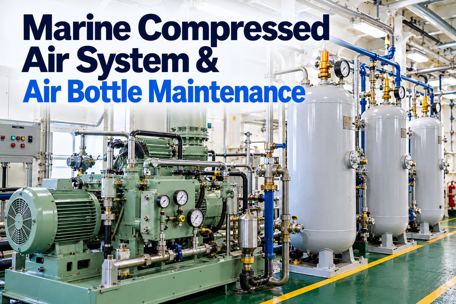
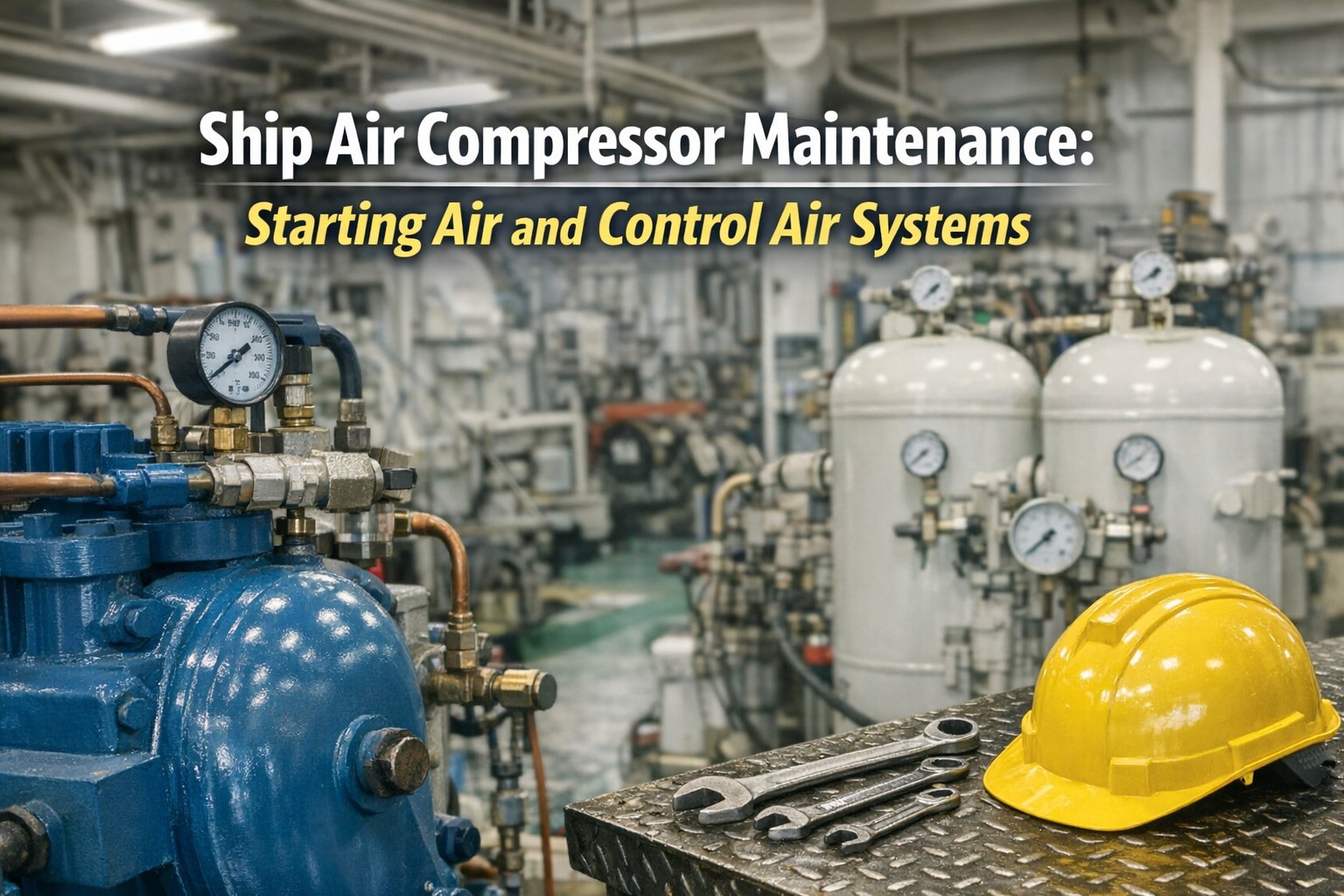
Marine Compressed Air System & Air Bottle Maintenance 2026
Compressed air is the system that starts everything else. Without it the main engine will not turn, the auxiliaries will not come on load, and a blackout stops being an inconvenience and becomes a drift. It is also the system with the most stored energy in the engine room, held in steel bottles at around thirty bar, which is why air receivers, relief valves and starting air lines are treated so seriously by class and by Port State Control. The failure modes are well known and almost entirely preventable: moisture and oil accumulating where they should have been drained, a leaking cylinder starting valve heating a manifold, a relief valve that has not lifted in years, a compressor running hot because its cooler is fouled, or a slow leak that quietly takes the receiver below the pressure needed for the starts the rules assume you have. This guide covers what the rules require of the system, how to maintain compressors and receivers, how to keep water and oil out, how air line explosions happen and how to prevent them, and the testing and records that prove all of it. Every figure is general guidance, and the maker's manual and class rules govern your installation. To keep drain records, relief valve tests and receiver inspections with the equipment, try Marine Inspection free.
30bar
Typical receiver pressure
12starts
Reversible main engine, no recharge
60min
To charge receivers from atmospheric
Stored energy, stored risk, and the reason the engine starts at all
Drain it, cool it, test the relief valves and keep oil out of the lines. Everything else on this page supports those four habits.
The detail sits in class rules rather than in one convention regulation, and the figures below are the ones most commonly applied. Check your own society's rules and the ship's documentation for the numbers that apply to you.
Two receiversAt least two air receivers of approximately equal capacity, each with a drain, a pressure gauge, a relief valve and access for internal inspection.
12 or 6 startsTotal receiver capacity without replenishment for not less than 12 consecutive starts of a reversible main engine, alternating ahead and astern, or 6 for a non-reversible engine.
3 starts eachCommonly applied to engines driving generators, including the emergency generator, and to other engines, with the consumption of connected services taken into account.
Two compressors, one hourTwo or more compressors with a total capacity able to charge the receivers from atmospheric pressure within one hour, with at least one independent of the main propulsion unit.
Separation of linesCompressor discharge pipes lead directly to the receivers, and starting air pipes from the receivers to the engines are kept entirely separate from the compressor discharge system.
Discharge temperatureAir temperature to the receiver is commonly limited, with 93 °C quoted as the ceiling, because hot air plus oil is what makes an explosion possible.
Relief valve accumulationCompressor safety valves sized and set so that, with the outlet closed, pressure accumulation does not exceed 10 per cent of the maximum working pressure.
Cooling space protectionWater jacket and cooler casings protected by a relief valve or bursting disc, so a burst air cooler tube cannot over-pressurise the water side.
Flame arresters or bursting discsRequired in way of each cylinder starting valve on direct reversing engines with a starting air manifold, or at the manifold inlet on non-reversing engines. Commonly omitted for bores not exceeding 230 mm.
Receiver pressure falling through consecutive starts
Illustrative. The capacity rule assumes the receivers are full and the engine is cold and ready to start. A receiver left part-charged, a leaking start valve bleeding air, or a heavy leak in the control air system all eat into the margin before anyone counts the starts. That is why the pressure at departure, and the leak rate overnight, are worth logging.
The system, stage by stage
Most faults are easier to place once you follow the air from the compressor inlet to the cylinder.
CompressorTwo-stage reciprocating, with intercooler and aftercooler, unloaders and its own lubrication
Coolers and separatorsWhere most of the water comes out, if the drains work
Air receiversStorage, with drains, relief valves, gauges and inspection access
Starting air lineAutomatic valve, non-return, flame arresters or bursting discs, slow turning arrangement
Distributor and cylinder valvesAir delivered in firing order, then shut off cleanly
Control and service airReduced pressure, dried and filtered for instruments, automation and whistle
Compressor maintenance
Compressors are simple machines that tolerate neglect until they do not. Most of the routine is about heat, oil and valves.
Valves and rings
Suction and discharge valve plates, springs and seats cleaned and inspected on the maker's interval
Piston rings and liner wear, which shows first as rising discharge temperature and longer charging time
Carbon deposits on valves and in the discharge passage, which are fuel for a fire
Cooling
Intercooler and aftercooler cleanliness on both sides
Cooling water flow, temperature rise across the unit and the relief arrangement on the water side
Interstage pressure, which is the earliest indicator of a valve or cooler problem
Lubrication
Correct grade and level, and the right oil for a compressor rather than whatever is nearest
Oil carryover checked at the separator and in the receiver drains
Crankcase breather and bearing condition
Controls and protection
Unloader operation on start and stop, and automatic start and stop pressures
Safety valve on each stage, lifted and reset on the planned interval
High temperature and low oil pressure cut-outs tested and recorded
Drains
Automatic drains proved to operate, not assumed
Manual drains on the planned schedule, with what came out noted
Drain lines clear, since a blocked drain hides the water it should be removing
Running data
Time to charge from a known pressure, trended against the baseline
Discharge temperature, interstage pressure, running hours and starts per hour
Noise and vibration, and any change in the sound of the unloader
Air receivers: the part that cannot be repaired at sea
A receiver is a pressure vessel. Its safety depends on wall thickness, a working relief valve and the absence of standing water inside it.
Drain daily, and after every chargeWater collects at the bottom of every receiver. Draining is the single most valuable routine in the whole system, and the quantity is worth noting because a rising trend means the coolers or separators need attention.
Relief valveTested and, where fitted, sealed after setting. A relief valve that has never lifted cannot be assumed to work.
Internal inspectionOpened for internal examination at the interval class requires, with the internal surface, especially the bottom, checked for corrosion and pitting and the condition recorded with photographs.
FittingsGauge accuracy against a test gauge, isolating and drain valves free, fusible plug where fitted, and the manhole door joint and securing arrangement.
External conditionCoating, supports, and any wastage at the saddles. Corrosion under supports is common and easy to miss.
DocumentationVessel certificate, working pressure marked, last inspection and any thickness measurements kept with the ship's records.
Water and oil: the two contaminants that matter
Compressing air heats it and squeezes water out of it. Both of those facts create the two problems below, and both are managed by draining, cooling and clean lubrication.
Water
Corrodes receivers and lines from the inside, where nobody sees it
Carries into control air and disrupts pneumatic instruments and valves
Can enter a cylinder through the starting air line, which is what the slow turning arrangement protects against
Freezes in deck lines in cold climates, blocking service air
Managed by: working drains at every low point, coolers and separators in good order, and air dryers for control air.
Oil
Carryover from worn compressor rings deposits in lines and receivers
Oil plus air plus heat is the recipe for a starting air line explosion
Deposits build up in the very places that are hardest to inspect
Contaminates control air and fouls instruments and valve actuators
Managed by: correct oil and level, compressor overhaul on the maker's interval, separators drained, and discharge temperature kept down.
Preventing a starting air line explosion
This is the failure that damages the engine room rather than the machine. It needs three things present at once: oil, air and a source of heat. Remove any one of them and it cannot happen.
1
Keep oil outMaintain the compressor so carryover stays low, drain separators, and clean deposits from lines and manifolds when the opportunity arises.
2
Find leaking cylinder starting valvesA leaking valve lets hot combustion gas into the manifold. Feel or measure branch pipe temperatures after starting: a hot branch is the classic sign.
3
Keep the protective devices in orderFlame arresters clean and fitted, bursting discs intact and the correct type, and the automatic valve's non-return function proved.
4
Drain before startingBlow through the lines and use the slow turning arrangement so water in a cylinder is found before full starting air is admitted.
5
Respect the interlocksTurning gear interlock and indicator cocks are procedural protections against the other way this goes wrong.
6
Investigate any bang or unusual startAn abnormal noise on starting is a reason to stop and inspect, not something to note and carry on with.
Control and service air
Control air is lower pressure but higher quality. Instrument and automation failures often trace back to moisture or oil rather than to the instrument.
Reducing stationPressure setting, filter and regulator condition, and the standby supply arrangement.
Air dryersOperation, regeneration cycle where applicable, and the condition of the desiccant. Check the dew point achieved if instrumentation allows.
Filters and separatorsElements changed on differential or time, with what is found in them recorded.
Emergency supplyWhere control air is backed up from the starting air system, prove the changeover works and know what it costs in starts.
DistributionLeaks hunted down with a soap solution at planned intervals, because small leaks add up to a compressor running continuously.
Deck and service airHoses, couplings and pressure settings, and drains at low points in cold weather.
Testing and records
WhatTypical frequencyWhat to record
Receiver and separator drainsDaily, and after chargingQuantity and appearance of what came out
Compressor running dataWeeklyCharging time, discharge temperature, interstage pressure, hours
Automatic drain functionWeeklyProved operating, not assumed
Safety and relief valvesPer maker and classSet pressure, lifting pressure observed, resealing
Protection cut-outsPer maker and classSet point and the value at which it operated
Compressor overhaulRunning hours per manualValve and ring condition, measurements, parts fitted
Receiver internal inspectionPer class survey cycleInternal condition, corrosion, photographs, thickness where taken
Leak surveyPlanned intervalLeaks found and rectified, and overnight pressure drop
Drain quantities, relief valve tests and receiver photos in one recordLog the routine where it happens, offline, and the trend that predicts a corroded receiver or a failing compressor is already there when the surveyor asks.
Hot starting air branch pipeCylinder starting valveLeaking or stuck starting valve. Treat as urgent, explosion risk
Pressure falling overnightLine leaks, valve seats, drains left openLeaking joints or valves, passing non-return, control air leaks
Engine fails to start on airPressure, interlocks, distributor, control airLow receiver pressure, turning gear interlock, distributor fault, control air low
Safety valve lifting in serviceSet pressure, pressure switch, unloaderPressure switch out of adjustment, unloader fault, valve set low
Frequently asked questions
How many starts must the air receivers provide?
Commonly not less than 12 consecutive starts for a reversible main engine, alternating ahead and astern, or 6 for a non-reversible engine, without replenishment. Generator and emergency generator engines are commonly assessed at 3 starts each, with connected consumers taken into account.
How quickly must the compressors be able to charge the receivers?
Two or more compressors are normally required with a total capacity able to charge the receivers from atmospheric pressure to the required pressure within one hour, with at least one independent of the main propulsion unit.
Why are flame arresters or bursting discs fitted?
To stop a flame or pressure wave from a cylinder travelling back into the starting air system. They are fitted in way of each cylinder starting valve on direct reversing engines with a manifold, or at the manifold inlet on non-reversing engines, and are commonly omitted for bores not exceeding 230 mm.
How often should air receivers be drained?
Daily as a minimum, and after charging. Note what comes out, because a rising water quantity means the coolers, separators or drains need attention.
What causes a starting air line explosion?
Oil deposits in the lines, air, and a source of ignition, most often a leaking cylinder starting valve admitting hot gas into the manifold. Controlling oil carryover and finding leaking valves early are the two practical defences.
What records will a surveyor ask for?
Receiver inspection and relief valve test records, compressor overhaul history, protection device test results and the drain routine. See our auxiliary engine guide and alarm and monitoring guide.
Prove the starts are there before you need them
Marine Inspection records drains, charging times, relief valve tests and receiver inspections at the machine, offline, links them to running hours, and builds the survey pack from the same data.