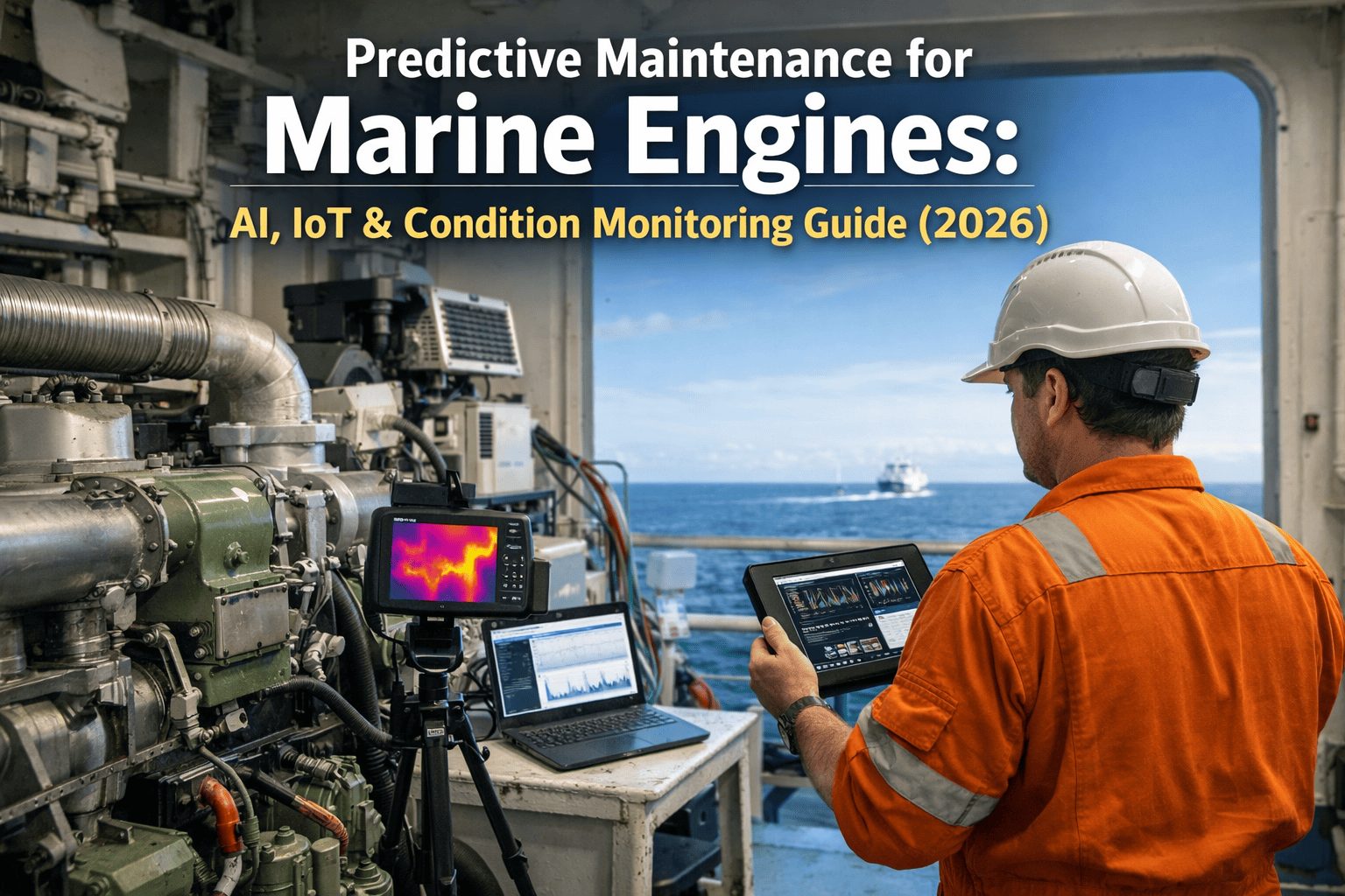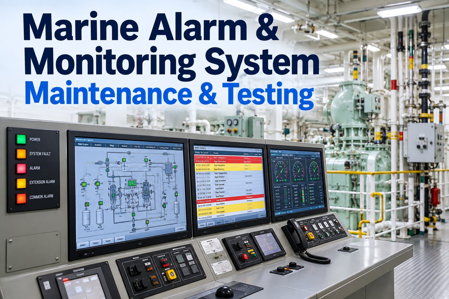
An alarm system is the only crew member that never sleeps, and on an unattended machinery space ship it is the reason the engine room can be left at all. It is also the system most likely to be quietly degraded: a sensor drifting out of calibration, a set point widened to stop a nuisance alarm, a cable repaired but never recalibrated, an extension alarm that stopped reaching one cabin months ago. None of that shows up in daily operation, because the system looks healthy right up to the moment it needs to be right. This guide covers what the alarm and monitoring system has to do under the SOLAS unattended machinery space requirements, the daily and periodic testing that proves it still does it, how to calibrate and loop-check sensors, and how to deal with the single biggest threat to a working alarm system, which is not a failed sensor but a flood of alarms nobody reads any more. The charts on this page use published alarm management benchmarks from process industry practice, because the shipping industry has no equivalent numbers and the human limits are the same. To keep test results, calibration records and set points with the equipment they belong to, try Marine Inspection free.
Prove the chain end to end: sensor, set point, panel, extension, cabin, bridge. Then record the value it actually tripped at.
What the rules expect the system to cover
The requirements for ships operating with periodically unattended machinery spaces sit in SOLAS Chapter II-1, Regulations 46 to 53, with class rules and the ship's notation adding detail. These are the headline items your testing programme has to prove.
The alarm numbers nobody measures on ships
Marine alarm systems are engineered to class rules but almost never measured against alarm management benchmarks. Process industry guidance is worth borrowing, because the limit is the human being reading the panel, not the ship. The widely used figures come from EEMUA 191 and ISA-18.2.
Roughly one alarm per ten minutes in steady state, about 144 to 150 a day, is the benchmark these standards converge on. A study of 37 operator consoles found around a third achieved it and about a quarter more reached the manageable band, so it is demanding but realistic.
The commonly cited target is roughly 80% low, 15% medium and 5% high. When priorities inflate towards an even split, every alarm carries the same weight and the system has communicated no priority at all. On a ship that means the duty engineer treats a bilge level and a jacket water temperature the same way at 0300.
Review the priority assigned to every alarm point when you review set points. It costs nothing and it is the single change that makes a panel readable.
A flood is commonly defined as more than ten alarms in ten minutes for one operator, and the flood is treated as continuing until a period carries fewer than five new alarms. This is exactly when the duty engineer most needs the panel to be readable, and exactly when an unrationalised system buries the one alarm that matters.
Alarm activity is always skewed. Published experience is that fixing the worst offenders, by correcting set points, adding suppression logic or removing the point, can cut overall alarm rates by 60 to 80 percent, and in one documented case seven alarms accounted for 98 percent of the load. That makes the first month of cleaning up an alarm list the cheapest safety work on the ship.
Nuisance alarms and how to kill them properly
The wrong way to deal with a repeating alarm is to widen the set point or disable the point. Both leave the panel quiet and the protection gone. Deal with the cause, and record whatever you change.
Sensor calibration and loop checks
Calibration proves the reading. A loop check proves the whole chain from sensor to panel to extension. Both are needed, and they are not the same test.
Resistance elements and thermocouples: compare against a reference at two points across the working range, check the transmitter output, and confirm the panel reading and alarm point. Watch for cable and terminal resistance on long runs.
Apply a known pressure with a calibrator, check zero and span, confirm the milliamp output, then confirm the panel value. Check impulse lines and isolating valves for blockage first, which is the more common fault.
Float and capacitance devices need functional testing by raising the actual level where practicable. Confirm the alarm and any automatic start, and check for fouling, which is the usual cause of failure.
Check against a second indication and against expected values at known load. Drifting flow measurement often shows up first as a control problem rather than an alarm.
Test and maintain strictly to the maker's instructions, including the test function, sampling pipe cleanliness and any lens or optics. This is a protection device, not an indication.
Simulate at the sensor, not at the card, wherever possible. Confirm the value at the panel, the alarm priority, the audible signal, the extension to cabins and public spaces, and the bridge indication.
The testing programme
Split testing by how much disruption it causes, so nothing waits for an opportunity that never comes. The exact frequencies come from your safety management system, the class notation and the maker's manual.
Dead man alarm and the lone engineer
When the machinery space is unattended and someone enters it alone, the dead man or patrolman system is the only thing that will raise the alarm if they are hurt. Practice varies between ships: some systems require the timer to be reset at intervals of around ten to twenty-five minutes, and where no system is fitted the usual requirement is for the engineer to contact the bridge at intervals not exceeding fifteen minutes. Follow the ship's own procedure, and test it rather than assuming it.
Keeping the system itself alive
The monitoring system is a machine too, and its failure modes are boring: a flat battery, a failed power supply card, a corrupted configuration with no backup, or a laptop nobody can find the password for.
Troubleshooting matrix
Frequently asked questions
SOLAS Chapter II-1, Regulations 46 to 53 cover fire detection, flooding detection, bridge control of propulsion, the engineers' alarm and the monitoring arrangements. Class rules and the ship's notation add the detail, including the test programme.
Engines of 2,250 kW and above, or with cylinders of more than 300 mm bore, require oil mist detection, bearing temperature monitoring or an equivalent arrangement.
Process industry guidance converges on about one alarm per ten minutes in steady state, roughly 144 to 150 a day, with more than ten in ten minutes counted as a flood. There is no marine equivalent, but the human limit is the same.
Only as a deliberate, recorded engineering decision against the maker's figures, never as a quick fix. Fix the cause, or add the correct deadband or delay, and write down what was changed and why.
At the interval in the safety management system, commonly before each unattended period as part of the checklist, and as a full functional test with the extension chain at the periodic interval.
UMS checklists, alarm and trip test records with set points and measured trip values, calibration records with reference instruments, the inhibit register and the configuration backup record. See our auxiliary engine guide and switchboard inspection guide.
Marine Inspection records alarm tests, calibration values and inhibit registers at the panel, offline, links them to the equipment and running hours, and builds the survey pack from the same data.