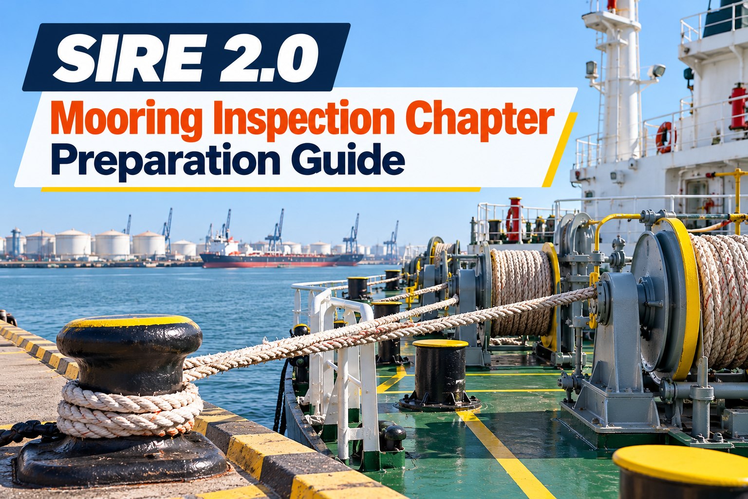
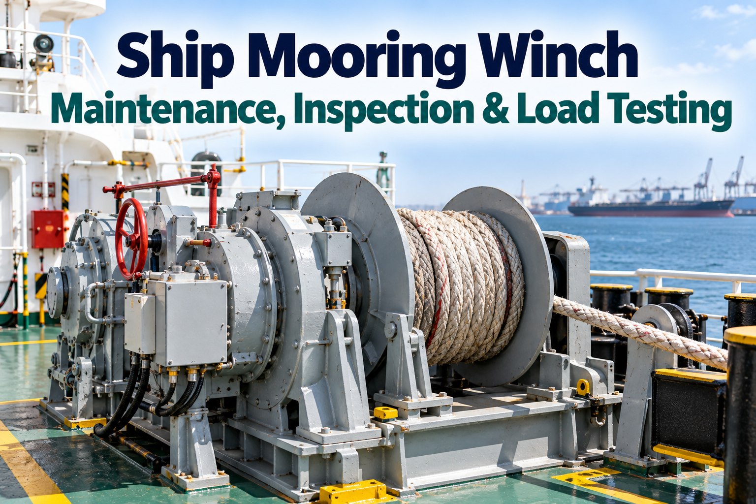
Chapter 9 of the question set covers mooring and anchoring, and it has a characteristic that sets it apart from most of the inspection: nearly every question resolves to a number somebody on board has to be able to produce. What the line is certified to, what the system was designed around, what the brake renders at, what retires a line. A mooring deck in excellent physical condition still answers the chapter badly if the officer cannot connect the rope in front of him to the figure on its certificate.
SIRE 2.0 · Chapter 9
Mooring is the chapter where the paperwork and the deck must agree
The register says what each line is, the certificate says what it will break at, the drum says what the brake holds, and the deck shows the condition. An inspector walks the mooring deck carrying those four things in mind, and the gaps between them are the observations.
The figures the chapter turns on
Three proportions govern how a mooring system is specified and operated under current industry guidance. An officer who knows these is most of the way through the conversation; one who does not will be asked a follow-up for every answer.
100–105%
Line strength against the ship design figure
A mooring line’s design break force is specified as a proportion of the vessel’s ship design minimum breaking load, so the line matches the system rather than being chosen for convenience or price.
125–130%
Tail strength against the same figure
Tails are deliberately stronger than the lines they are fitted to, so that if something has to fail it does not fail at the shore connection. A tail weaker than its line inverts the design intent.
~60%
Where the winch brake should render
The brake is set to slip under overload rather than hold until the line parts, and the holding capacity is tested and marked on the drum — which makes it the single most verifiable figure on the deck.
The brake figure is the one most often challenged in an inspection, because it is physically marked and therefore checkable against a test record in a way the others are not.
Four strength terms that are not interchangeable
A great deal of confusion in mooring discussions comes from using one word for four different things. The terms below describe different quantities and an officer mixing them up signals that the system is understood loosely.
MBL
Minimum breaking load, the older term
The breaking load of a new, dry line as declared by the maker. Its weakness was that it invited the reading that a line could safely be worked anywhere up to that figure, which is not what it describes at all.
SDMBL
Ship design minimum breaking load
The reference strength for the vessel’s whole mooring system, worked out against standard environmental criteria. It belongs to the ship rather than to any individual rope, and everything else is specified against it.
LDBF
Line design break force
The minimum force at which a new, dry, spliced line breaks under the standard test, declared on that line’s own certificate. Nylon is the exception, tested wet and spliced. This is the figure that belongs to the rope in front of you.
WLL
Working load limit
What the line should actually be worked to in service, a fraction of the figures above. The distance between this and the break force is the safety the system was designed to carry, not spare capacity to be used.
The register, line by line
The mooring equipment register is what turns those terms into something a vessel can be held to. Each line is tracked individually, and the inspector’s questions follow the columns.
| Recorded against each line |
Why it is asked about |
A weak record |
| Identity and position | Which physical line this is and where it is rigged, so a record can be matched to a rope on deck | Lines recorded by type only, with no way to tell one from another |
|---|
| Certificate and break force | The declared design break force for that line, and the certificate behind it | A certificate for the batch rather than for the line, or one nobody can produce |
|---|
| Date entered service | Age in service, which drives inspection frequency and retirement judgement | Supply date recorded instead of the date it was first rigged |
|---|
| Loads it has seen | Overloads, snatch events and heavy weather, which age a line faster than time does | No event history, so a line that has been shock loaded looks like one that has not |
|---|
| Inspection results | What each examination found, by whom, with the condition described rather than scored | A run of identical entries saying satisfactory, which reads as unexamined |
|---|
| Retirement criteria | The thresholds that will take this line out of service, set in advance | No criteria recorded, leaving retirement to a judgement made on the day |
|---|
| Rotation and position changes | Where the line has been used, since some positions work a rope far harder than others | Lines never moved, so the same ropes take the heaviest leads for their whole life |
|---|
Equipment on the anchoring side carries its own history in the same way, and the practical maintenance of it is covered in our guide to anchor and mooring equipment maintenance.
Two plans, one deck
Mooring System Management Plan
Covers the arrangement as a whole — the design basis, the equipment fitted, how the system is meant to be used and maintained. It is the document that explains why this vessel moors the way she does, and it is the one an officer should be able to reason from rather than recite.
Mooring Line Management Plan
Covers the lines themselves, supported by the equipment register. Service entry, loads seen, inspections and the retirement criteria for each rope. This is the plan that produces decisions, and the one most often thin in practice.
Inspectors tend to approach these from opposite ends: the system plan through questions to the master and chief officer, the line plan through the register and the deck. Both have to agree with what is rigged, and where they disagree the disagreement is the finding — you can see in a short demo how the plan, the register and the line history are held together.
The rope on deck and the record of it, in one place
Marine Inspection holds each line as an item with its certificate, service date, load events and inspection history attached, so matching the deck to the register stops being a paper exercise before every port call.
Snap-back, and the problem with a painted line
Marked snap-back zones were once standard practice and are now treated with considerably more caution, for a reason worth understanding rather than simply complying with: the zones are estimates, and a painted boundary invites a crew to read the area outside it as safe. Paint on a deck cannot make an area safe.
The older approach
Zones marked on deck
Crew positioned outside the paint
Implied safety beyond the line
Static, whatever the arrangement
The current direction
The deck treated as live whenever lines are under load
People kept clear of the direct line of a lead
Numbers on deck minimised during heaving and tensioning
Hazards briefed for the arrangement actually in use
For an inspection this matters less as a marking question than as a behaviour one. What an inspector sees during an actual mooring operation — where people stand, how many are on deck, whether anyone is in line with a loaded rope — answers more of the chapter than any document does.
Brake holding capacity, tested and marked
The winch brake is the most verifiable item in the whole chapter, which makes it the most exposed. The figure is marked on the drum, so the only question is whether a test record supports it.
1The marking agrees with the record
The holding capacity shown on the drum matches the last test, and the test was carried out by a method the vessel can describe. A marking nobody can trace back is worse than no marking.
2The setting matches the line in use
The brake is set against the characteristics of the rope actually fitted. Changing to a different line without revisiting the brake setting quietly breaks the relationship the design relies on.
3The test interval is real
Tested at the stated frequency and recorded, with any winch that failed and was adjusted shown as such. A fleet where every winch passes every test for years invites attention.
4The crew know what rendering means
That the brake is intended to slip under overload rather than hold, and why. An officer who treats rendering as a defect has described the system backwards.
Retirement decided in advance
The weakest part of most line management is the moment of retirement, because it is usually a judgement made by whoever is looking at the rope on the day it matters commercially least convenient to change it.
Criteria set before the line enters service
Written into the plan and the register so the decision is a comparison rather than an opinion. Defined in advance and applied, rather than deciding at the time whether a line looks serviceable.
Events counted as well as wear
A rope that has been shock loaded has aged in a way that an external examination may not show. The load history in the register is doing work the eye cannot.
Retired samples used to check the criteria
Residual strength testing of lines taken out of service tells an operator whether their thresholds are right for their own trade, which is the only way to know if the criteria are conservative or optimistic.
Replacement planned, not reactive
Lines approaching their criteria visible in advance, so a replacement is ordered before the rope has to be condemned alongside with nothing to replace it.
RGRegister and documents
Every line on board appears individually in the register
Each has a certificate that can be produced within minutes
Service entry dates reflect first use, not the date of supply
Retirement criteria are written down for each line type
Both the system plan and the line plan exist and describe this vessel
DKDeck and practice
Brake holding capacity is marked and supported by a test record
Tails are the stronger element, matched to the lines fitted
Nothing is mixed on the same service without a reason recorded
Crew keep clear of loaded leads without being told during the operation
The officer in charge can state what the brake renders at and why
The right-hand column is observed rather than discussed, and most of it is settled in the first ten minutes of a mooring operation. Wider preparation across the question set sits in our SIRE inspection checklist, and you can book a demo to see line records and brake tests held against each vessel.
Marine Inspection modules for the mooring chapter
Vessel RecordsEquipment Register · Certificates · Line History
Holds each mooring line as an individual item with its certificate, design break force, service entry date and position history, so the register is a live record rather than a document rebuilt before an inspection.
MaintenancePlanned Routines · Brake Test Records · Defect Register
Schedules winch brake testing at its stated interval and keeps the result against the winch, including the ones that needed adjustment, which is what makes the figure marked on the drum defensible.
InspectionLine Inspections · Checklist Builder · Finding Register
Runs line examinations with the condition described rather than scored, flags lines approaching their retirement criteria, and carries any finding through to verified closure.
Document ControlSystem Plan · Line Plan · Procedures
Keeps the mooring system and line management plans at their current revision at the point of use, so the plan an officer reasons from is the one that describes the equipment currently fitted.
Crew & CompetenceFamiliarisation · Duty Assignment · Training Records
Records who has been taken through the mooring arrangement and which station each person works, which is what supports the behavioural half an inspector watches during the operation itself.
Reporting & AnalyticsFleet Dashboard · Replacement Forecast
Shows lines nearing retirement and overdue brake tests across the fleet, turning replacement into procurement planned in advance rather than a rope condemned alongside with nothing to put in its place.
Mooring chapter preparation: frequently asked questions
Which chapter covers mooring?
Chapter 9, Mooring and Anchoring, in the published question library, sitting between the cargo and ballast chapter and the machinery spaces chapter.
What is the difference between MBL, ship design MBL and line design break force?
Minimum breaking load is the older term for a new dry line’s declared breaking load. Ship design minimum breaking load is the reference strength of the vessel’s whole mooring system, calculated against standard environmental criteria. Line design break force is the minimum force at which a new, dry, spliced line breaks under the standard test, declared on that line’s own certificate, with nylon tested wet.
Why are tails stronger than the lines?
Lines are specified at roughly 100 to 105% of the ship design figure and tails at roughly 125 to 130%, so that if anything fails it does not fail at the shore connection. A tail weaker than its line reverses that intent and is a finding in its own right.
What should the winch brake be set to?
To render at around 60% of the line’s breaking load, so that it slips under overload rather than holding until the rope parts. The holding capacity should be tested and marked on the drum, which makes it the most readily verified figure on the deck.
Should snap-back zones still be painted on deck?
The practice is treated with much more caution than it once was, because the zones are estimates and a painted boundary can be read as a safe area. The current direction is behavioural: treat the deck as live whenever lines are under load, keep people out of the direct line of a lead, minimise numbers during heaving and tensioning, and brief the hazards of the arrangement actually in use.
How should lines be retired?
Against criteria defined in advance and applied, rather than deciding on the day whether a rope looks serviceable. The register should carry the loads a line has seen as well as its inspection results, and residual strength testing of retired samples is how an operator checks whether their thresholds suit their own trade.
Chapter 9 readiness
Make the numbers producible and the deck will follow
Marine Inspection keeps every line as a tracked item with its certificate and history, schedules and records brake testing against each winch, and flags lines approaching retirement — so the register, the certificate, the drum and the rope all say the same thing.