Marine Switchboard & Electrical Distribution Inspection
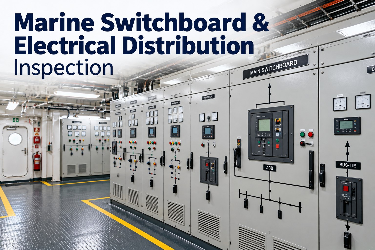
The main switchboard is the one space on board where a small oversight becomes an immediate, irreversible event. A loose busbar connection heats for weeks before it fails, a drifting insulation reading precedes an earth fault that trips a generator at the worst moment, and a breaker that has not been serviced may not clear the fault it was fitted to clear. Switchboard work also carries the highest personal risk in the engine department, so every routine below starts with isolation, not with a screwdriver. This guide covers what to inspect on main and emergency switchboards, group starter panels and distribution boards: insulation resistance testing and how to read the trend, thermal checks, air circuit breaker upkeep, bus-tie and interlock arrangements, and the records class and Port State Control expect to see. Only competent, authorised people should carry out this work, following the ship's permit system and the maker's manual. To keep the readings and photos with the equipment record rather than in a folder, try Marine Inspection free.
Electrical inspection guide
Heat, moisture and a drifting megger reading
Almost every switchboard failure announces itself in one of those three ways first. The routines here are about catching them while the board is still healthy.
Test at 500 V d.c. on a 440 V system. A commonly applied minimum for these circuits is 1 MΩ.
Before anything else: isolation and safe access
No inspection routine is worth an arc flash. Live work on a main switchboard should be the exception, covered by a specific risk assessment and procedure, never a habit.
Non-negotiables before the panel is opened
Permit and planWork permit raised, the bridge and duty engineer informed, and the consequences of losing that section understood
Isolate and lockIsolate, lock off, tag, and keep the key with the person doing the work
Prove deadTest the tester, prove dead at the point of work, then test the tester again
Discharge and earthDischarge capacitors and apply earths where the system requires it
Insulated standingMatting in front of and behind the board, dry, intact and in place
Never aloneA second person present, trained in rescue and first aid for electric shock
Know the distribution before you inspect it
An inspection is only meaningful if you know what each section feeds and what happens when it is lost. Walk the single line diagram before the panel doors open, and mark the inspection points on it.
GeneratorsDG 1, 2, 3 and shaft generator
Emergency generatorSeparate space, own supply
Main switchboardSections A and B, joined by the bus-tie breaker
Emergency switchboardFed by interconnector, isolated on blackout
Group starter panelsPumps, fans, compressors
Transformers 440/220 VLighting and services
Distribution boardsAccommodation, deck, navigation
Shore connectionInterlocked with generators
Inspection points: busbar joints, breaker contacts, earth fault monitor, interlocks, cable glands and terminations at every level.
The routine, by opportunity
Some checks need nothing more than a walk past the board. Others need the section dead, which usually means planning around a blackout opportunity or a yard period. Group them so nothing waits for an opening that never comes.
WhenChecksRecord
In service, weeklyEarth fault lamps or monitor readings, load balance between phases and sets, panel meters against actual load, unusual noise, smell or discolouration, panel heaters and ventilation working, doors and interlocks intactReadings and anything abnormal, with the circuit identified
In service, monthlyThermal or temperature check of accessible joints at load, insulation resistance of feeders that can be isolated individually, synchronising and load sharing checks, alarm lamp testTemperatures compared with neighbouring joints, megger values trended
Dead board opportunityBusbar and terminal tightness to the maker's torque, contact condition, arc chutes, cleaning of dust and salt, insulation resistance of busbars and main feeders, interlock functionTorque values, before and after photos, megger readings
Annual and surveyBreaker servicing to the maker's schedule, protection testing including secondary or primary injection, earth fault monitor calibration, emergency switchboard proving, documentation reviewTest sheets with set points and results, signed and dated
Insulation resistance: read the trend, not the number
Insulation resistance testing on a 440 V system is normally carried out with a 500 V d.c. instrument. A minimum of 1 MΩ is commonly applied to these circuits, but a reading just above the minimum is not a pass to be filed and forgotten. What matters is the direction of travel, and readings are temperature sensitive, so log the conditions with the value.
Test voltage500 V d.c. for 440 V systems. Lower voltages may be permitted for circuits under 250 V, subject to the rules that apply to your ship.
Minimum value1 MΩ is widely applied as the acceptable minimum for these installations. Check the figure in your class rules and flag guidance.
TemperatureInsulation resistance falls as temperature rises. A common rule of thumb is that the value roughly halves for every 10 °C increase, so record the temperature with the reading.
What to disconnectIsolate the circuit and disconnect or bypass sensitive electronics before testing, following the equipment manual.
Falling readingsLook for moisture, salt, dust, oil, damaged glands and failing heaters. Clean and dry first, then retest before condemning a machine.
Keep the logShips normally carry a dedicated insulation resistance log. Trending the same circuits over time is what makes the data useful.
Isolated, tested, recorded
Capture megger values, torque settings and panel photos at the board, offline, so the next reading has something to trend against and the surveyor gets a complete file.
Heat is the earliest symptom of a loose or corroded connection. Thermal imaging of a board under load, carried out safely and without opening live compartments unnecessarily, shows joints that are running hotter than their neighbours. Industry guidance notes that thermographic imaging can be accepted towards survey requirements, so agree the scope with your surveyor before the survey rather than after.
1Survey under real loadA cold board tells you nothing. Record the load at the time of the scan.
2Compare like with likePhase against phase, and a joint against the same joint on an identical feeder.
3Photograph both waysKeep the thermal image and a normal photograph of the same spot, labelled with the circuit.
4Act on the outlierAny joint clearly hotter than its neighbours gets isolated, cleaned and retorqued, then rescanned.
Air circuit breakers and protection
The breaker is the last line of defence for the generator and the busbar. Servicing is on the maker's schedule, and testing is what proves the settings are still what the coordination study assumed.
Mechanical
Main and arcing contact wear, alignment and pressure
Arc chutes clean, undamaged and correctly fitted
Closing and tripping mechanism, springs and charging motor
Racking mechanism, shutters and safety interlocks
Lubrication exactly as the manual specifies, and no more
Electrical and protection
Trip unit tested by secondary injection, or primary injection where required
Overcurrent, short circuit, reverse power and undervoltage settings recorded against the coordination study
Preferential trip operation and timing
Auxiliary contacts, indication and remote signals
Insulation resistance across the poles and to earth
Record the settings, not just the testA protection test without the set points written down proves nothing later. Note the setting found, the setting left, the injected value and the measured trip time.
Bus-tie, interlocks and configuration
How the board is split decides what survives a fault. Main busbars on ships where electrical power is needed for propulsion are required to be divided into at least two parts, normally joined by circuit breakers, with generators and duplicated equipment shared between them as far as practicable.
Bus-tie closedSimplest operation and full load sharing, but a busbar fault can take the whole board. Check the protection discrimination that protects against this.
Bus-tie openSections independent, so a fault is contained. Each side must have its own generation and the duty split must be understood by the watch.
Emergency interconnectorFeeds the emergency board in normal service and must open on main power failure so the emergency generator takes its own board.
Shore supply interlockPrevents paralleling shore power with the generators unless the system is designed for it. Test the interlock, do not assume it.
Findings that come up again and again
Insulated matting missing, torn or wet in front of the board
Earth fault indication ignored because "it clears itself"
Insulation resistance log with gaps, or the same value copied each month
Breaker maintenance overdue, with no record of the last service
Protection settings not matching the single line diagram or coordination study
Spare fuses of the wrong rating, or fuse carriers repaired with wire
Panel doors with missing screws, damaged seals or defeated interlocks
Cable glands loose, grommets missing, or unused openings not blanked
Frequently asked questions
What test voltage is used for shipboard insulation resistance testing?
A 500 V d.c. instrument is normally used for 440 V systems, with lower test voltages permitted for circuits under 250 V depending on the applicable rules.
What is the minimum acceptable insulation resistance?
1 MΩ is widely applied as the minimum for these installations. Treat it as a floor, not a target, and act when the trend is falling towards it.
Can thermal imaging replace opening the board?
It cannot replace the maker's servicing, but industry guidance notes it can be accepted towards survey requirements for identifying hotspots. Agree the scope with your surveyor in advance.
How often should breakers be serviced?
On the maker's schedule, adjusted for operating hours and number of operations, with protection testing aligned to the class survey cycle.